Touch Panel and Touch Panel Type Display Apparatus

US20100201640A1Active Publication Date: 2010-08-12KYOCERA CORP

Image

  • Touch Panel and Touch Panel Type Display Apparatus
  • Touch Panel and Touch Panel Type Display Apparatus
  • Touch Panel and Touch Panel Type Display Apparatus

Examples


Embodiment Construction

[0044]Hereinafter, a touch panel and a touch panel type display apparatus according to an embodiment of the present invention will be described with reference to the drawings.

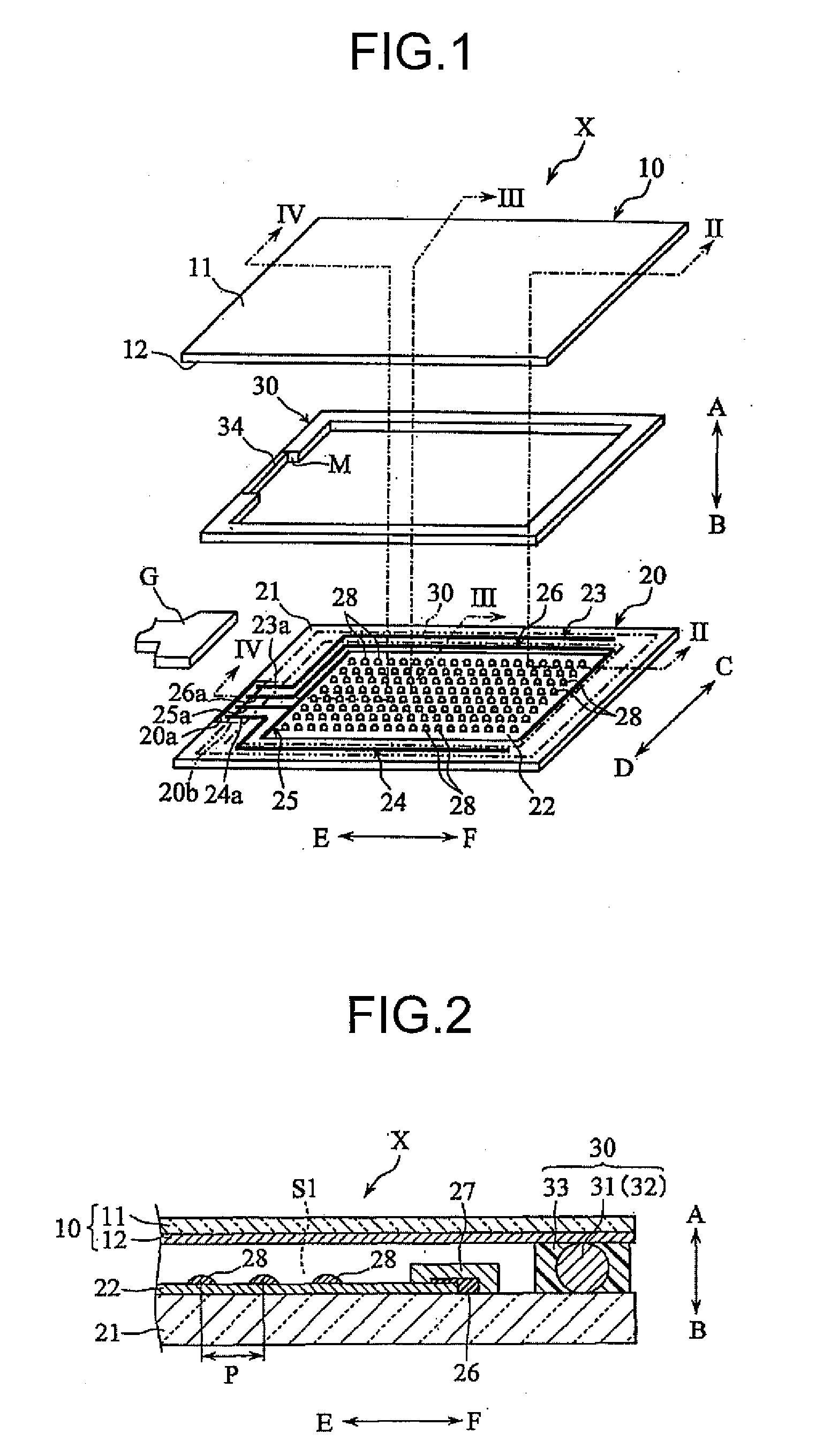
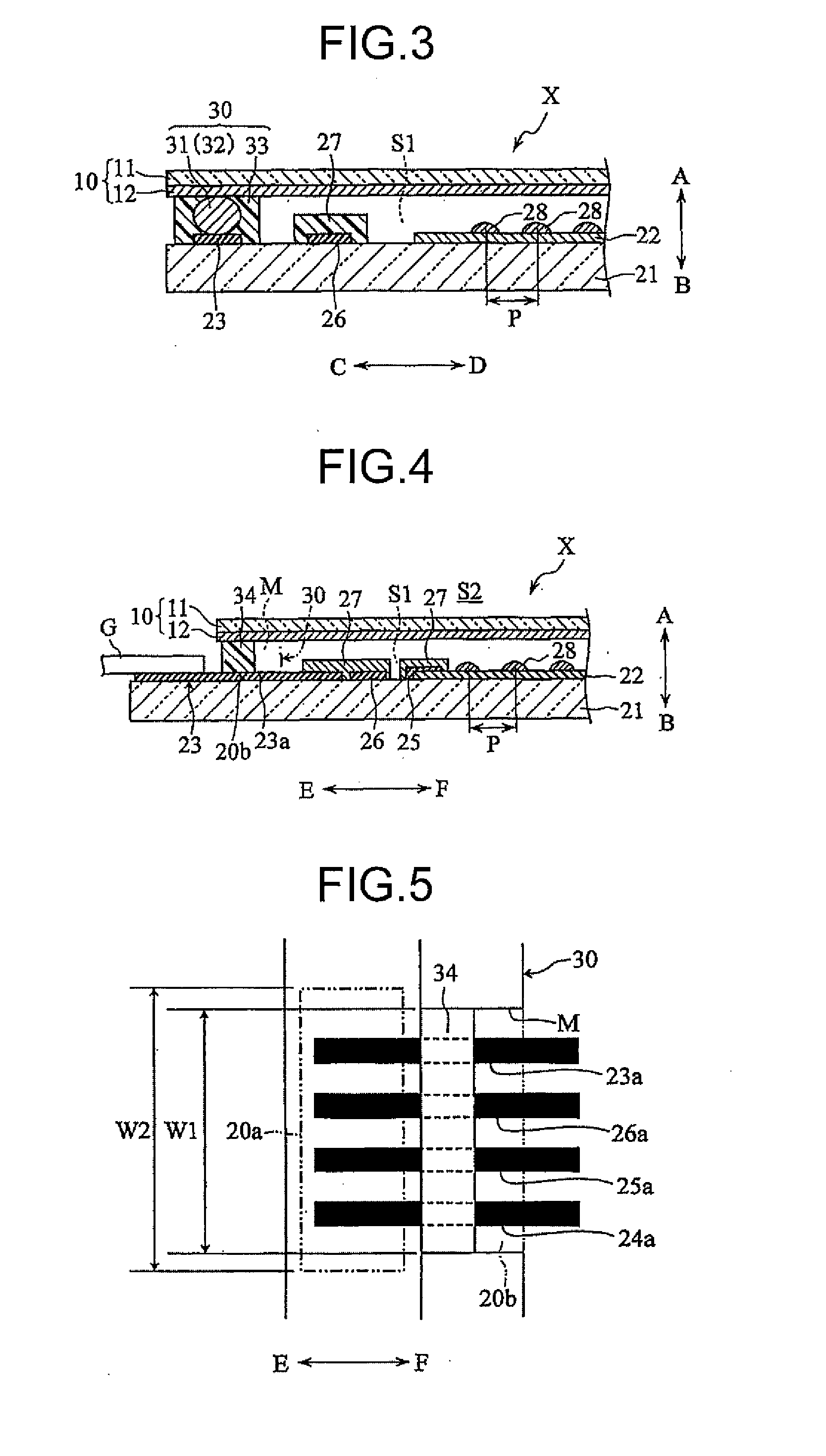
[0045]First, a touch panel X and a touch panel type display apparatus Y according to the present embodiment will be described with reference to FIGS. 1 to 9.

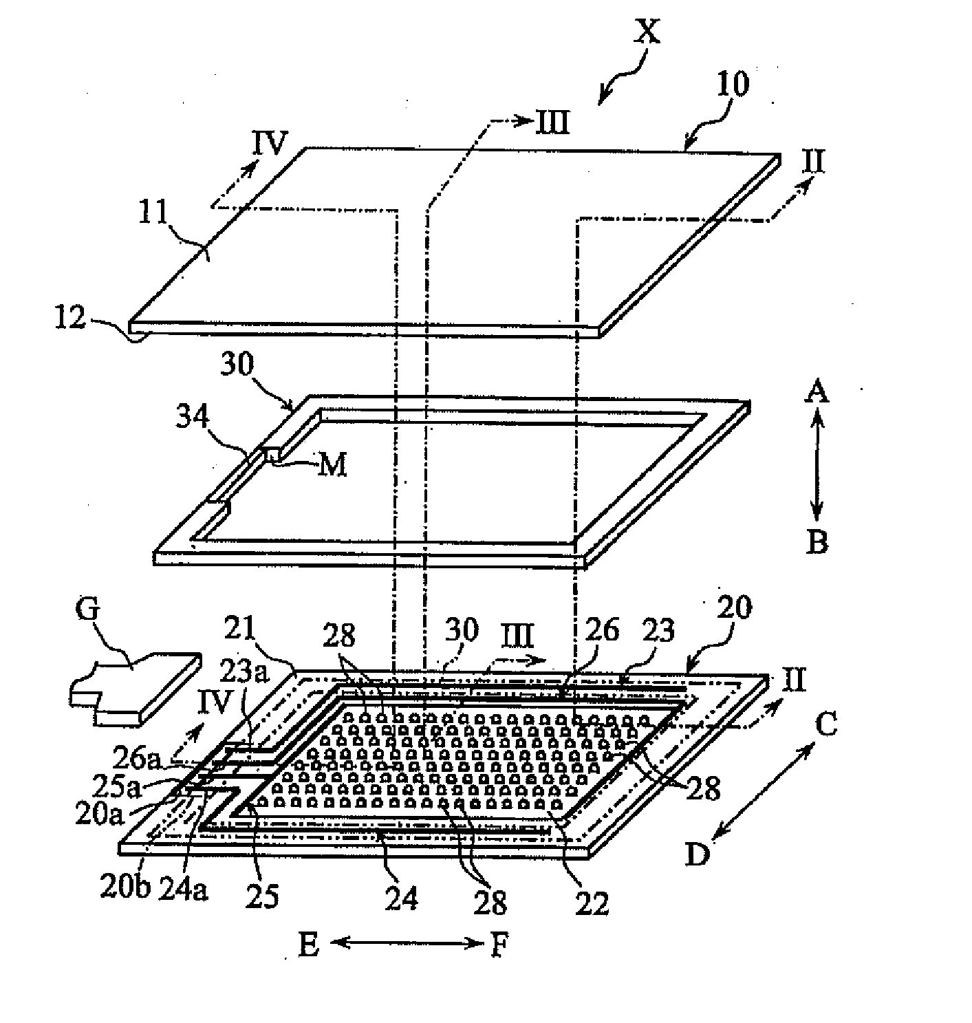
[0046]As illustrated in FIGS. 1 to 4, the touch panel X includes a first base body 10, a second base body 20, and a conductive adhesive member 30.

[0047]The first base body 10 has flexibility as a whole, and has a generally rectangular shape in a plan view. The plan view shape of the first base body 10 is not limited to a generally rectangular shape, but may be any other shape. The first base body 10 includes an insulating substrate 11 and a first resistive film 12.

[0048]The insulating substrate 11 is a member having a role for supporting the first resistive film 12, and has a translucency and electrical insulating properties in a direction crossing the main...


PUM


Abstract

A touch panel X in accordance with the present invention includes a first base body 10 including a first resistive film 12, a second base body 20 including a second resistive film 22 and a wiring electrodes 23 and 24, and a conductive adhesive member 30 configured to electrically connect the first base body 10 and the wiring electrodes 23 and 24, and bond the first base body 10 and the second base body 20 so that the first resistive film 12 and the second resistive film 22 face each other. The conductive adhesive member 30 defines an internal space S1 and an opening portion M. The wiring electrodes 23 and 24 include connection portions 23a and 24a. The connection portions 23a and 24a are formed in an area corresponding to the opening portion M.

Description

TECHNICAL FIELD[0001]The present invention relates to a touch panel disposed on a display screen such as a liquid crystal display. The present invention further relates to a touch panel type display apparatus including a touch panel disposed on a display apparatus.BACKGROUND ART[0002]Touch panel type display apparatuses include, for example, an apparatus including a touch panel for detecting an input position by a resistance change caused by a pressing operation, which is disposed on a liquid crystal display (for example, refer to Japanese Patent Application Laid-open No. 2003-196030 and Japanese Patent Application Laid-open No. 2003-216339).[0003]The touch panel has a configuration in which an input panel is disposed to face a base panel. The base panel includes, on a surface facing the input panel, a transparent insulating base member made of a soda glass plate, a transparent electrode made of ITO formed in the center of the surface facing the input panel, a routed wiring which is...

Claims


Application Information

Patent Timeline
12 Aug 2010
Publication
US20100201640A1
IPC
G06F3/041
CPC
G06F3/045; G06F3/041; G06F3/04164
Inventors
NOZAWA, JUNICHI; KOJIMA, YUJI