Read and write power control methods and system for optical recording device

a power control and optical recording technology, applied in the field of read and write power control methods and optical recording device systems, can solve the problems of insufficient headers, insufficient headers, and unstable laser power emitted from the pickup head for a while, and achieve the effect of shortening the level transition of the read power control signal and shortening the level transition of the write power control signal

Active Publication Date: 2010-08-12
MEDIATEK INC
View PDF12 Cites 2 Cited by
  • Summary
  • Abstract
  • Description
  • Claims
  • Application Information

AI Technical Summary

Benefits of technology

[0010]Secondly, it is an alternative objective of the present invention to provide the read and write power control methods for an optical recording device capable of shortening level transition of the power control signal, even eliminating the level transition, and preventing an unstable power output for the pick-up head.
[0011]Thirdly, it is an alternative objective of the present invention to provide the read and write power control methods for an optical recording device capable of rapidly approaching an optimal level of the power control signal to induce proper powerneeded by the pick-up head.
[0012]To achieve the foregoing objectives, the present invention provides a read power control method for an optical recording device having a pick-up head. Before a start of a recording operation of the pick-up head, a specific level of a former read power control signal based on a former read power control (e.g. a close-loop control) is determined After the recording operation, during the pick-up head passes over respective header, a read power is rapidly induced by a predetermined level of the read power control signal which is set under a present read power control (e.g. an open-loop control) according to the specific level, and thereby shortening level transition of the read power control signal. Alternatively, if the present read power control is a close-loop control during the pick-up head passes over respective header, the read power can be rapidly induced by a predetermined level serving as an initial level of the read power control signal, which is set according to the specific level, for gradually approaching an optimal level.
[0013]Furthermore, the present invention provides a write power control method for an optical recording device. During a recording operation of the pick-up head, a specific level of a write power control signal based on a former write power control is determined When the pick-up head passes over respective headers, the former write power control is stopped. After the pick-up head passes over respective headers, a write power can be rapidly induced by a predetermined level of a write power control signal which is set under a write power control (i.e. a close or open loop) according to said specific level of the former write power control signal, and thereby shortening level transition of the write power control signal.

Problems solved by technology

Further referring to FIGS. 1C & 1D, each level transition of a read or write power control signal, under a turn of the power control, for example, from either a write power to a read power, or from a read power to a write power, would result in a unstable power output initially for a while.
Especially, if a difference / drop between the initial level and optimal level becomes enlarged because of an operating temperature rise, after each time of beginning of writing operation, the laser power emitted from the pickup head will be always unstable for a while.
However a period of reading the header is too short insufficient to sample an exact power signal into a power control loop to generate a proper power, especially in a high, multiple speed operation.
However, the level transition of a write power control signal under different power control loop (i.e. a close or open loop) may be too long and insufficient to supply the pick-up head with a steady write power.
It is apparent that unstable write power is greater proportioned to be involved in writing quality, especially under a high operation temperature.

Method used


Image

  • Read and write power control methods and system for optical recording device
  • Read and write power control methods and system for optical recording device
  • Read and write power control methods and system for optical recording device

Examples


Embodiment Construction

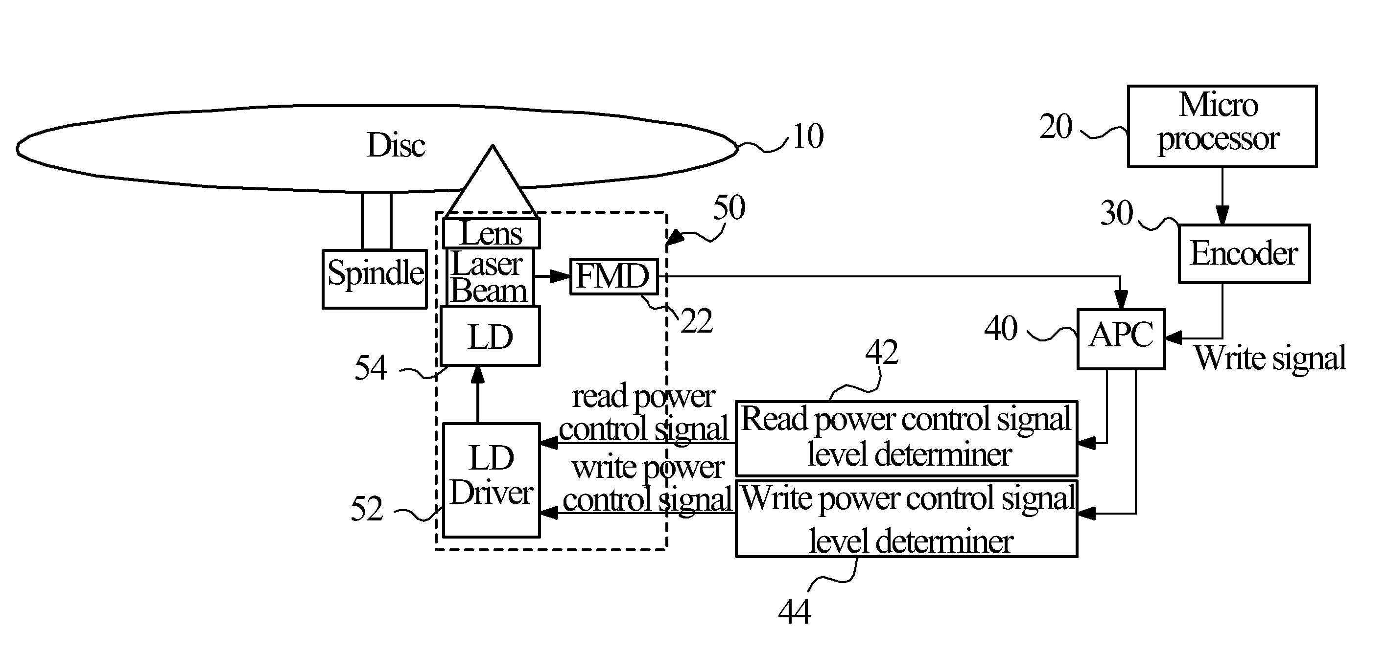
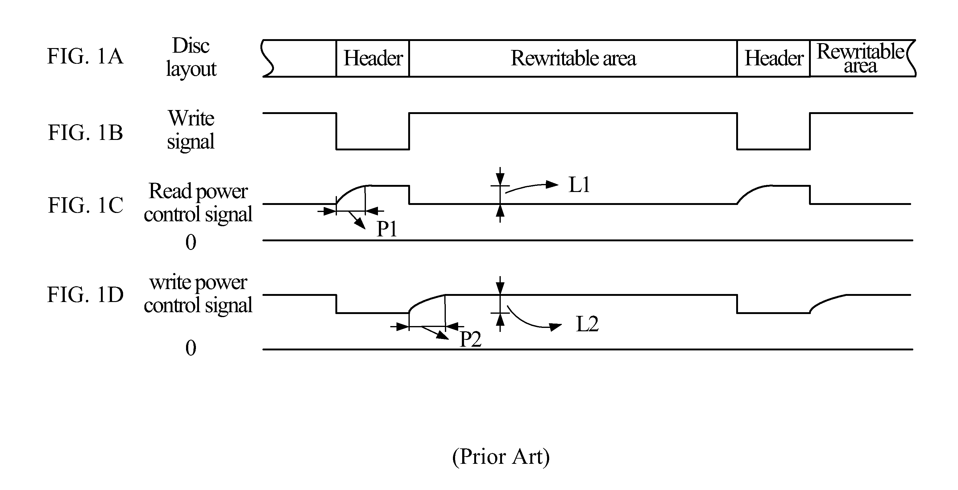
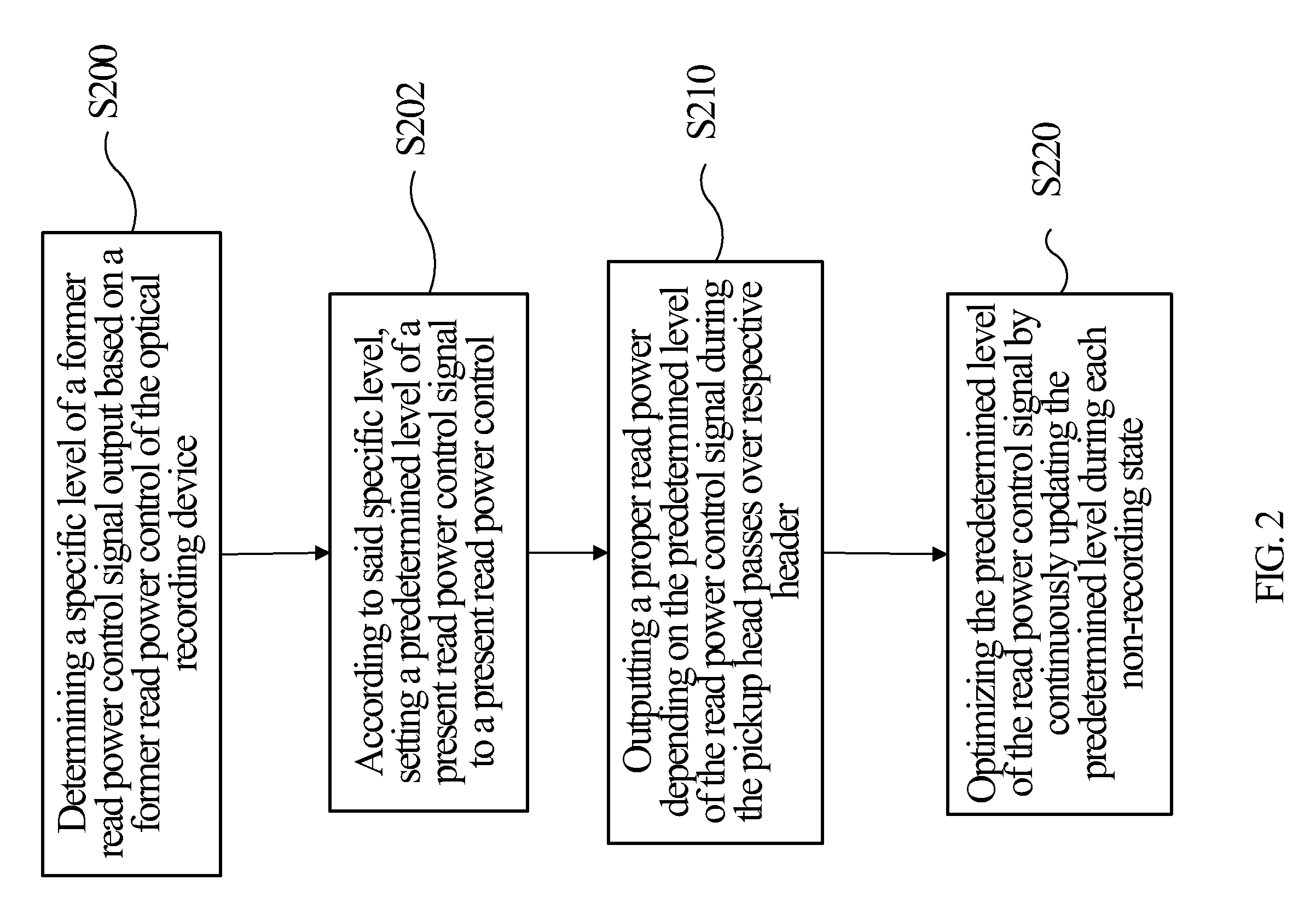
[0023]Firstly referring to FIGS. 2, 5A, 5B, and 5C, a read power control method of an optical recording device having a pick-up head for recording information on a corresponding optical disk (e.g. DVD-RAM). The optical disk should be embossed with a plurality of read-only areas interposed between the recordable areas, such as headers in DVD-RAM. According to a preferred embodiment of the present invention, the method comprises the following steps of:

[0024]In step S200, determining a specific level of a former read power control signal output based on a former read power control (i.e. a close-loop control) of the optical recording device, which induces a former read power supplied before a recording operation of the pick-up head starts for the corresponding optical disk;

[0025]In step S202, according to said specific level, setting a predetermined level of a present read power control signal to a present read power control (i.e. an open loop control). In an exemplar, before recording ...


PUM

PropertyMeasurementUnit
read poweraaaaaaaaaa
operating temperatureaaaaaaaaaa
laser poweraaaaaaaaaa

Abstract

The present invention discloses read and write power control methods and system for an optical recording device that records information on an optical disk having read-only areas. The read and write power control methods respectively introduce the steps of determining a specific level of a former power control signal output based on a former power control, and then according to the specific level, setting a predetermined level of a power control signal to induce a present power control for rapidly outputting a proper power of the pick-up head. Accordingly, the level transition of the read / write power control signal can be shortened and even eliminated. An unstable read / write power output for the pick-up head can be avoided.

Description

CROSS-REFERENCE TO RELATED APPLICATIONS[0001]This application is a division application of patent application Ser. No. 11 / 531,713, filed on Sep. 14, 2006, which claims the benefit of the filing date under 35 U.S.C. §119(e) of a Provisional U.S. patent application Ser. No. 60 / 725,090, filed on Oct. 7, 2005, which is incorporated by reference herein.BACKGROUND OF INVENTION[0002]The present invention relates to read and write power control methods and system of an optical recording device used for recording information on an optical disk that had read-only areas.[0003]Recently, various types of rewritable optical disk such as a DVD-RAM (Digital Versatile Disk Random Access Memory) or DVD-RW disks capable of reproducing digital data therein have come into wide use. In DVD-RAM disks, the stored information is consequently allocated in sector units. Each sector unit includes a read-only identification (ID) area (i.e. a header) and a rewritable area (i.e. user data area), as shown in FIG. ...

Claims


Application Information

Patent Timeline
Patent Type & Authority Applications(United States)
IPC IPC(8): G11B20/10G11B7/125
CPCG11B7/0045G11B7/1263G11B7/00745
Inventor WU, CHIH-CHUNGHUANG, CHI-PEIYU, MING-JIOU
Owner MEDIATEK INC
Why Eureka
Try Eureka