
Hydrogen producing apparatus, method of operating hydrogen producing apparatus and fuel cell power generating system
- Summary
- Abstract
- Description
- Claims
- Application Information
AI Technical Summary
Benefits of technology
Problems solved by technology
Method used
Image

Examples
embodiment 1
[0156]Hereinafter, a Hydrogen Generation Apparatus in Embodiment 1 according to the present invention will be described.
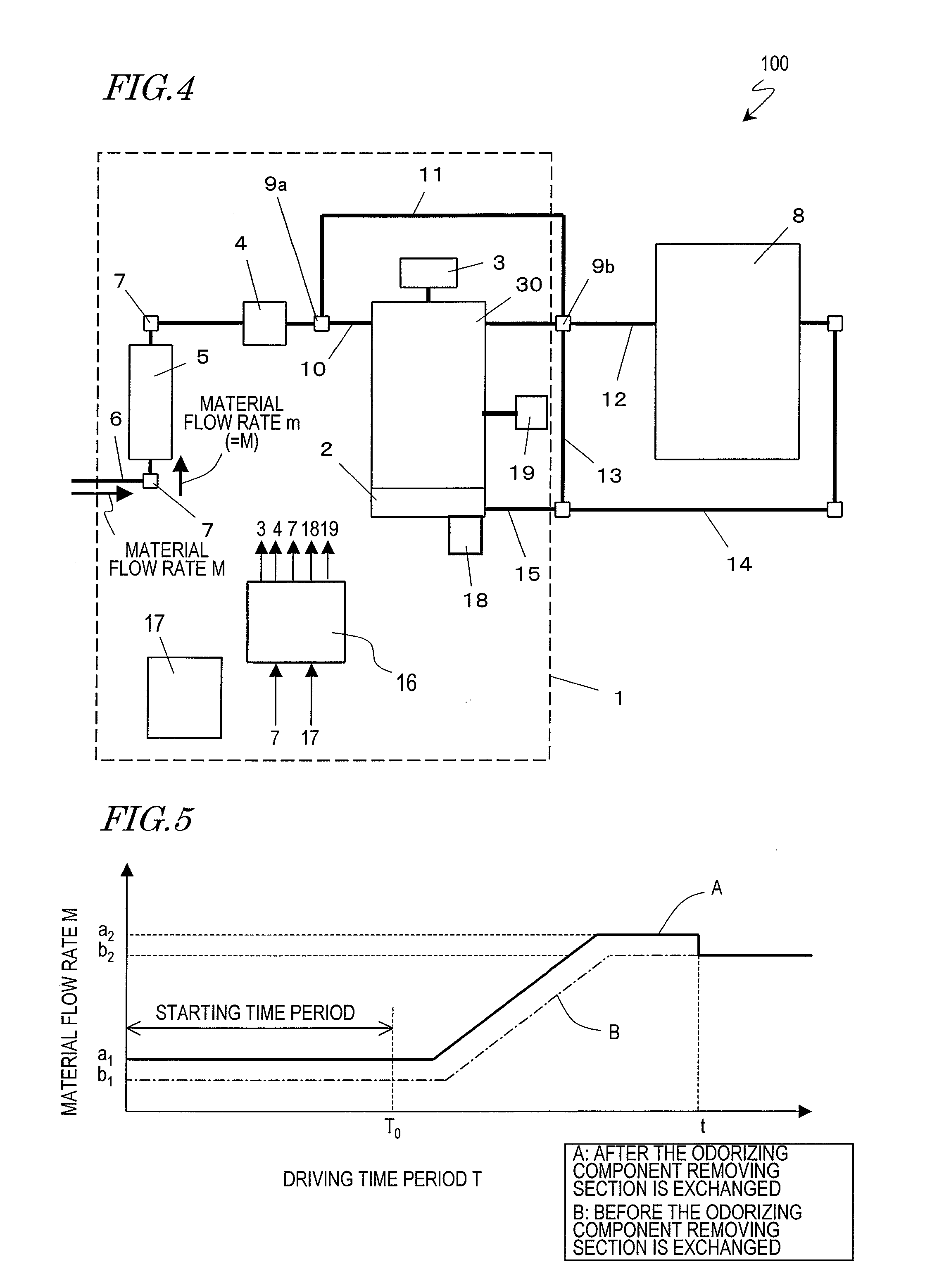
[0157]The hydrogen generation apparatus in this embodiment is an apparatus for generating hydrogen-containing gas using a hydrocarbon-based raw material containing a sulfur component. In order to remove the sulfur component from the raw material, an adsorbing desulfurization section for adsorbing the sulfur component is used. The adsorbing desulfurization section is detachably held in a holding mechanism provided in the hydrogen generation apparatus. When the adsorbing ability on the sulfur component is decreased, the adsorbing desulfurization section is exchanged to a new adsorbing desulfurization section, or only the adsorbing agent (adsorbing desulfurization agent) in the adsorbing desulfurization section is exchanged. Alternatively, the adsorbing desulfurization section may be regenerated. It is preferable that the adsorbing desulfurization section contains an ...
embodiment 2
[0214]FIG. 8 is a structural view of a hydrogen generation apparatus in Embodiment 2 according to the present invention. Unlike the hydrogen generation apparatus 1 shown in FIG. 4, the hydrogen generation apparatus in this embodiment is structured such that a part of the raw material supplied from the gas infrastructure line can be sent to the combustor as combustion gas without being passed through the adsorbing desulfurization section.
[0215]In the hydrogen generation apparatus 1 described above with reference to FIG. 4, the raw material which has passed the adsorbing desulfurization section 5 can be sent to the combustor 2 and combusted together with hydrogen off-gas (assist combustion). However, the gas to be combusted in the combustor 2 may contain an odorizing component and does not need to pass the adsorbing desulfurization section 5. Therefore, the hydrogen generation apparatus in this embodiment is structured such that the raw material which has not passed the adsorbing desu...
embodiment 3
[0220]Hereinafter, a hydrogen generation apparatus in Embodiment 3 according to the present invention will be described with reference to the figures.
[0221]FIG. 9 is a block diagram showing a structure of a fuel cell power generation system using the hydrogen generation apparatus in this embodiment. FIG. 10 is a flowchart showing particulars of a control program regarding the odorizing component removing member exchange / regeneration in the hydrogen generation apparatus shown in FIG. 9.
[0222]A fuel cell power generation system 500 shown in FIG. 9 includes a fuel cell 150, a hydrogen generation apparatus 200, and an oxidizing agent gas supply unit 160. The structure of the hydrogen generation apparatus 200 will be described in detail later.
[0223]In this embodiment, the fuel cell 150 is formed of a polymer electrolytic fuel cell. The polymer electrolytic fuel cell is formed as a fuel cell stack by a plurality of cells stacked and tightened. Each cell includes an MEA (not shown) having ...
PUM
 Abstract
Description
Claims
Application Information