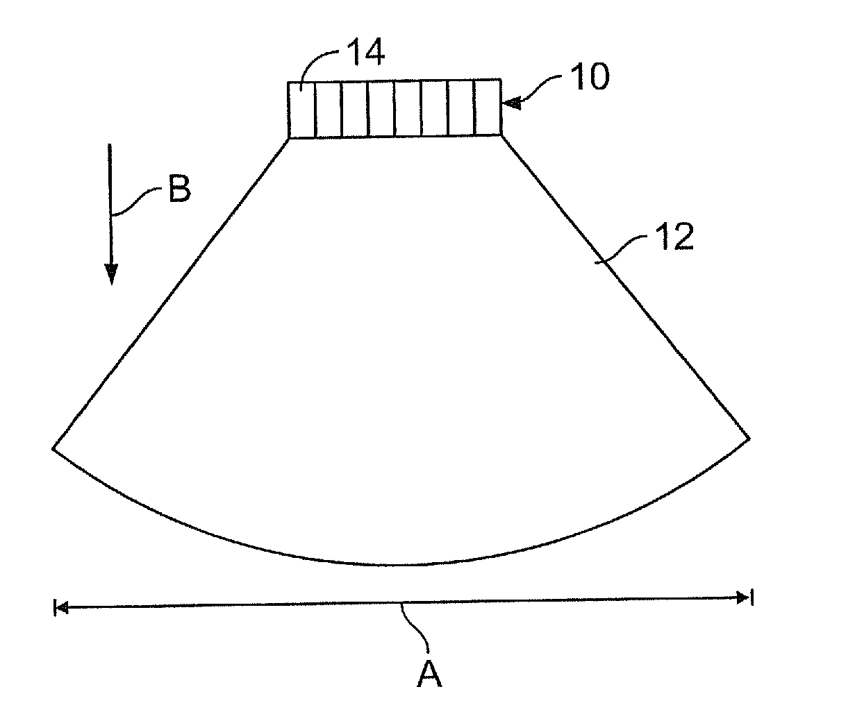
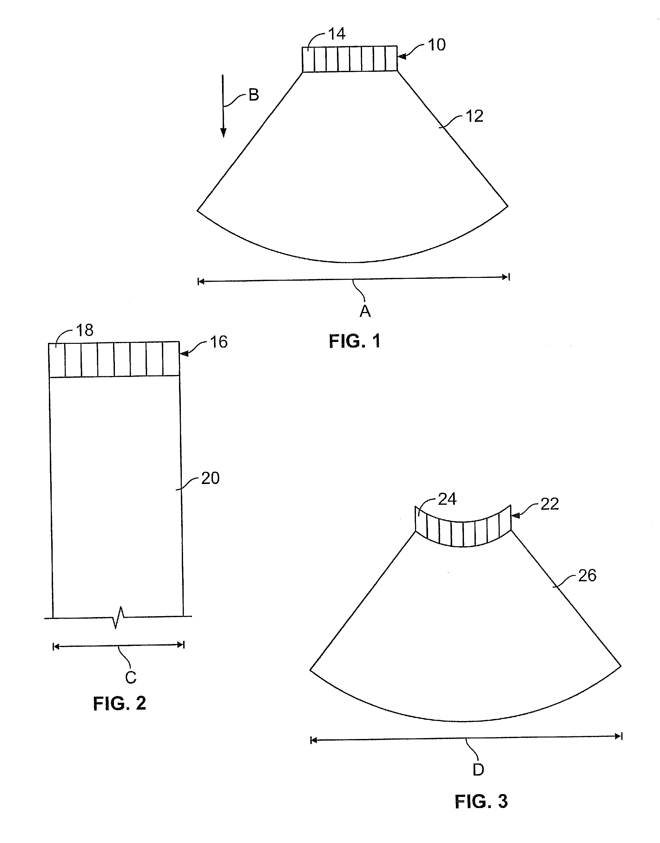
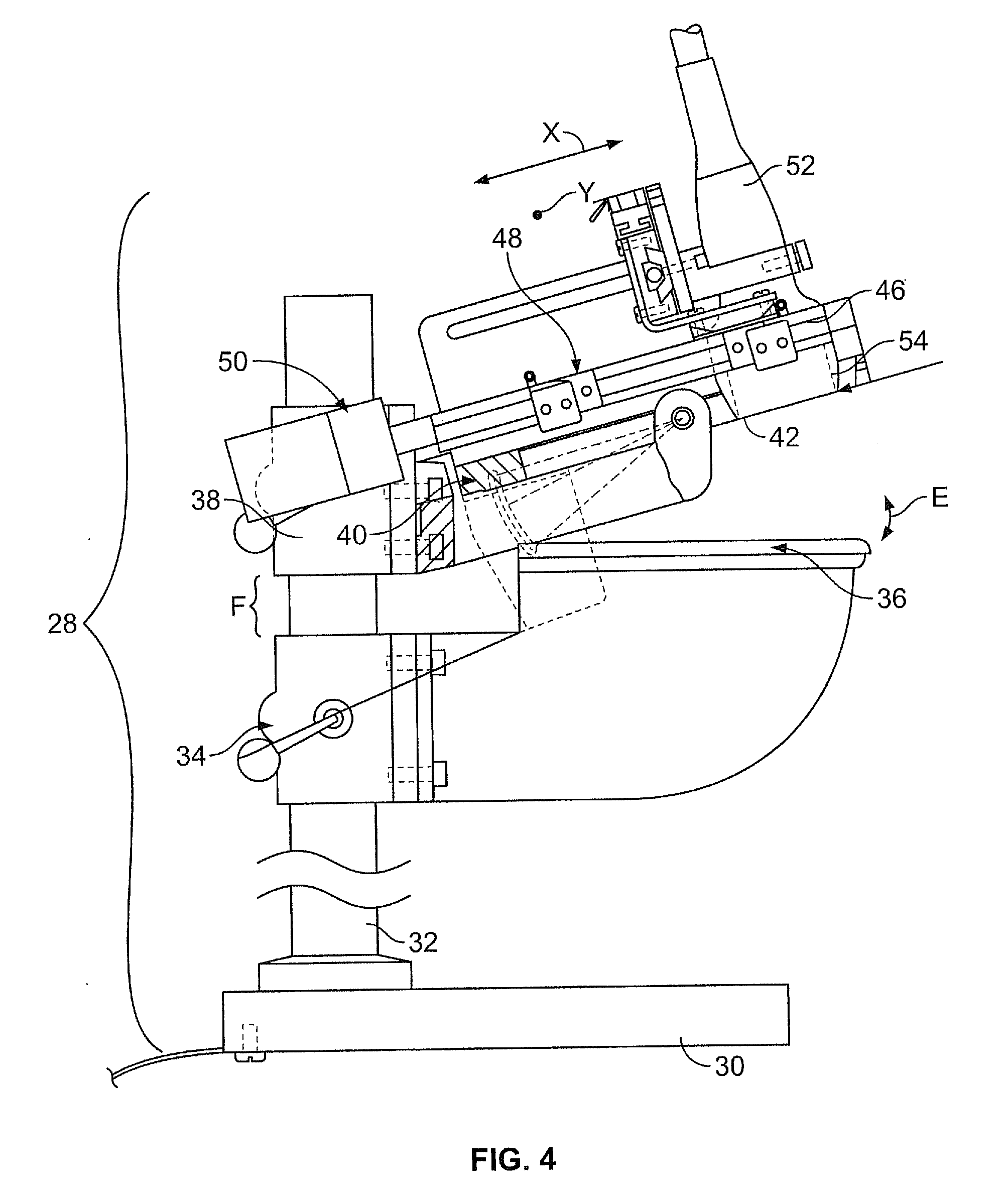
Ultrasound breast screening device

a breast screening and ultrasonic technology, applied in ultrasonic/sonic/infrasonic image/data processing, instruments, tomography, etc., can solve problems such as pain and overall discomfort, x-ray mammography, and various patient comfort issues

Inactive Publication Date: 2010-08-12
GENERAL ELECTRIC CO
View PDF88 Cites 5 Cited by
  • Summary
  • Abstract
  • Description
  • Claims
  • Application Information

AI Technical Summary

Benefits of technology

This patent describes a mechanism called a pivot assembly which lets two parts move back and forth without changing their positions. It can create pressure between them by using a spring-like connection.

Problems solved by technology

The technical problem addressed in this patent is the discomfort experienced by patients who require their breasts to be pressed together for a long period of time during a medical examination process. This can cause pain and fatigue. Additionally, current ultrasound imaging systems have limitations in accurately focusing on small targets like breast cancer cells without causing distortion. There is a need for a new ultrasound breast imaging system that offers better comfort and accurate target detection.

Method used


Image

  • Ultrasound breast screening device
  • Ultrasound breast screening device
  • Ultrasound breast screening device

Examples


Embodiment Construction

[0045]FIG. 15 is a schematic diagram of an ultrasound imaging system 100 according to an embodiment of the present invention. The ultrasound imaging system 100 includes an ultrasound imaging device 28, which is in electrical communication with a central processing unit (CPU) 102. The CPU 102 may control movement of an imaging transducer (discussed below) and the movement of compression plates (discussed below) of the ultrasound imaging device 28. The CPU 102 sends control commands to the ultrasound imaging device 28, and receives data signals from the ultrasound imaging device 28. The CPU 102 analyzes the data signals received from the ultrasound imaging device in order to form images for display. The CPU 102 is also in electrical communication with an imaging workstation 104, which displays image data received from the CPU 102. That is, the CPU 102 may send signals to, and receive signals from, the imaging workstation 104. A user may enter imaging and display commands through input...


PUM


Abstract

An ultrasound breast imaging assembly includes first and second compression plates angled with respect to one another, a breast compression area defined between the first and second compression plates, at least one pivot assembly, and an ultrasound probe. The pivot assembly allows relative motion between the first and second compression plates. The ultrasound probe, which is configured to translate over one of the first and second compression plates, includes an active matrix array (AMA) positioned on one of the first and second compression plates.

Description


Claims


Application Information

Patent Timeline
Owner GENERAL ELECTRIC CO
Why Eureka
Try Eureka