Bridge fault removal apparatus, bridge fault removal method, and computer readable medium comprising computer program code for removing bridge fault

a fault removal and fault technology, applied in the direction of resistance/reactance/impedence, testing circuit, instruments, etc., can solve the problems of high failure rate, high failure rate, and rapid increase of malfunction

Inactive Publication Date: 2010-08-12
KK TOSHIBA
View PDF7 Cites 0 Cited by
  • Summary
  • Abstract
  • Description
  • Claims
  • Application Information

AI Technical Summary

Problems solved by technology

When the interconnections become different potentials, a bridge failure incidence ratio in which a faulty signal propagates to the outside of LSI to cause a malfunction is rapidly increased.
However, in LSI used in a high-speed product manufactured through the microfabrication process, because ordinary IDDQ value is largely increased, the IDDQ test is hard.
In the bridge fault test, when accuracy of the test result exceeds a predetermined level, an effect that is obtained by improving the accuracy of the test result tends to be weakened.
However, it is extremely difficult to completely extract the pieces of information.
Particularly, in the bridge fault test for LSI, a large amount of CPU (Central Processing Unit) resource is necessary.
Therefore, the bridge fault test achieving the practical accuracy is hardly realized.
As a result, an undetected bridge fault always remains, and the bridge failure cannot be detected even if the bridge failure occurs in the pair of interconnections corresponding to the bridge fault.
Therefore, the bridge failure incidence ratio cannot sufficiently be reduced.
Additionally, in the ATPG tool, because some of the bridge faults remain undetected when only a few test patterns are used, a test quality is hardly improved.
As a result, since it is difficult to shorten an IDDQ measuring time compared with other test techniques (currently, at least one millisecond to several milliseconds are necessary for one pattern), a large effect cannot be obtained even if the ATPG tool is used in the IDDQ test in which the improvement of test quality is obtained by few test patterns.
Therefore, the cause of the bridge failure can be left unclear.
Therefore, it is difficult to lower the bridge failure incidence effectively by widen the distance between the proximity interconnection wires.
Therefore, the bridge failure incidence ratio in LSI cannot sufficiently be reduced by the conventional technique.

Method used


Image

  • Bridge fault removal apparatus, bridge fault removal method, and computer readable medium comprising computer program code for removing bridge fault
  • Bridge fault removal apparatus, bridge fault removal method, and computer readable medium comprising computer program code for removing bridge fault
  • Bridge fault removal apparatus, bridge fault removal method, and computer readable medium comprising computer program code for removing bridge fault

Examples


Embodiment Construction

[0041]Hereafter, an embodiment of the present invention will be described more specifically with reference to the drawings. The embodiment is described only by way of example, and the scope of the present invention is not limited to the embodiment.

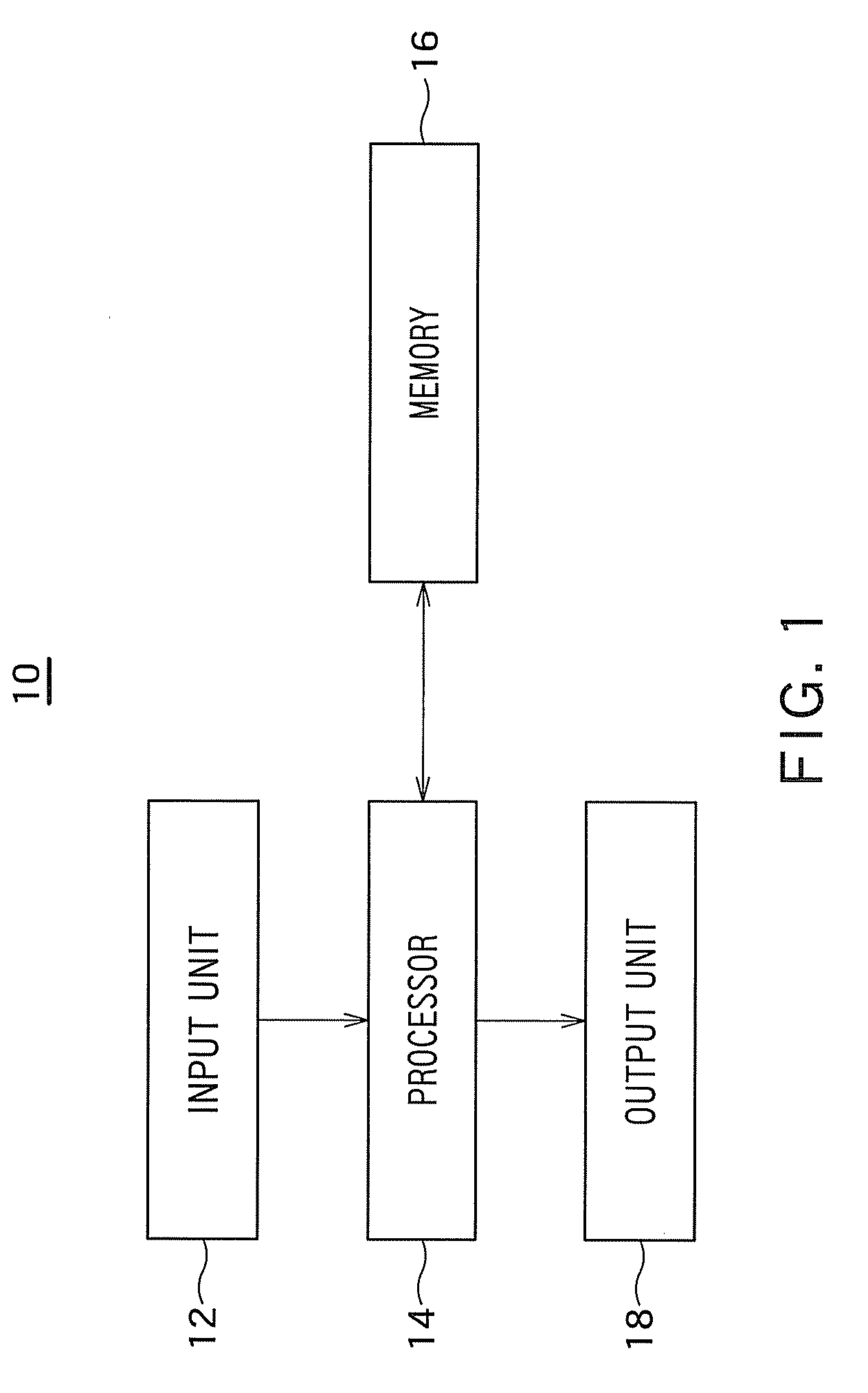
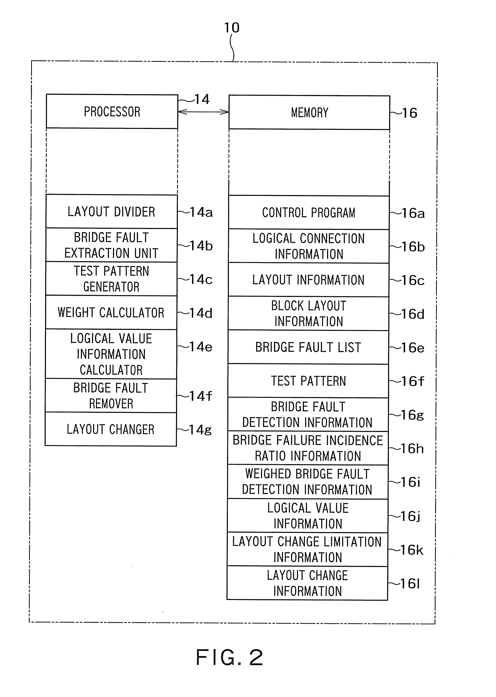
[0042]A configuration of a bridge fault removal apparatus 10 according to an embodiment of the present invention will be described with reference to FIGS. 1 and 2. FIG. 1 is a block diagram illustrating the configuration of the bridge fault removal apparatus 10 according to the embodiment of the present invention. FIG. 2 is a block diagram illustrating the detailed configuration of the bridge fault removal apparatus 10 illustrated in FIG. 1.

[0043]Referring to FIG. 1, the bridge fault removal apparatus 10 includes an input unit 12, a processor 14, a memory 16, and an output unit 18.

[0044]The input unit 12 is connected to the processor 14. The input unit 12 transmits information fed by a user to the processor 14. For example, examples of the...


PUM


Abstract

A bridge fault removal apparatus includes a bridge fault extraction unit configured to extract a bridge fault from layout information of a semiconductor integrated circuit, a test pattern generator configured to generate the test pattern aiming at the bridge fault extracted by the bridge fault extraction unit, a logical value information calculator configured to calculate logical value information of all the signals in the semiconductor integrated circuit by applying the test pattern generated by the test pattern generator to logical connection information of the semiconductor integrated circuit, and a bridge fault remover configured to select an exchange signal candidate for an undetected bridge fault signal corresponding to the test pattern based on the logical value information calculated by the logical value information calculator.

Description

CROSS-REFERENCE TO RELATED APPLICATION[0001]This application is based upon and claims the benefit of priority from the prior Japanese Patent Application No. 2009-026446, filed on Feb. 6, 2009; the entire contents of which are incorporated herein by reference.BACKGROUND OF THE INVENTION[0002]1. Field of the Invention[0003]The present invention relates to a bridge fault removal apparatus, a bridge fault removal method, and a computer readable medium comprising computer program code for removing bridge fault. Particularly the invention relates to the bridge fault removal apparatus, the bridge fault removal method, and the computer readable medium comprising computer program code for removing a bridge failure in a semiconductor integrated circuit such as LSI (Large Scale Integration) manufactured by a microfabrication process.[0004]2. Related Art[0005]In the recent semiconductor integrated circuit such as LSI, dust tends to adhere between interconnections to establish conduction with th...

Claims


Application Information

Patent Timeline
Patent Type & Authority Applications(United States)
IPC IPC(8): G06F19/00G01R31/00G01R31/3183G06F17/50H01L21/82H01L21/822H01L27/04
CPCG01R31/318364G01R31/2853
Inventor NOZUYAMA, YASUYUKI
Owner KK TOSHIBA
Why Eureka
Try Eureka