Steam assisted oil recovery and carbon dioxide capture

Inactive Publication Date: 2010-08-19
CONOCOPHILLIPS CO
View PDF9 Cites 24 Cited by
  • Summary
  • Abstract
  • Description
  • Claims
  • Application Information

AI Technical Summary

Problems solved by technology

Utilizing numerous separate components required to perform the independent processes adds to

Method used


Image

  • Steam assisted oil recovery and carbon dioxide capture
  • Steam assisted oil recovery and carbon dioxide capture
  • Steam assisted oil recovery and carbon dioxide capture

Examples


Embodiment Construction

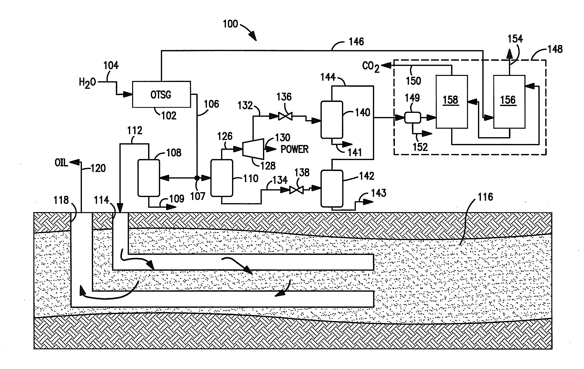
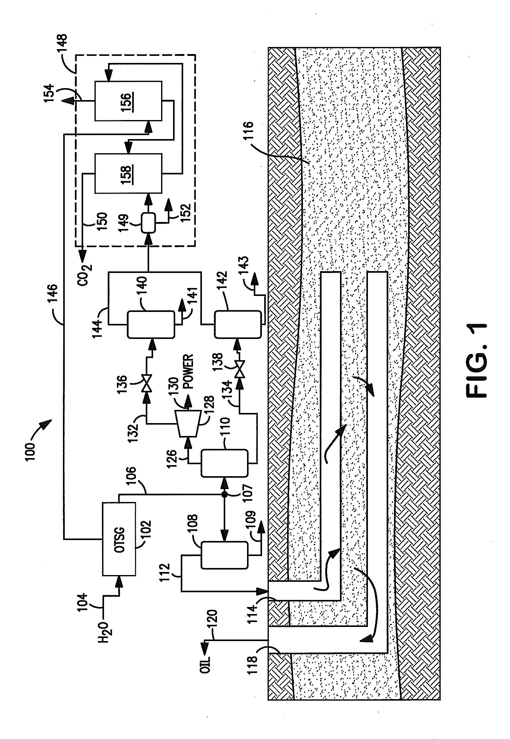
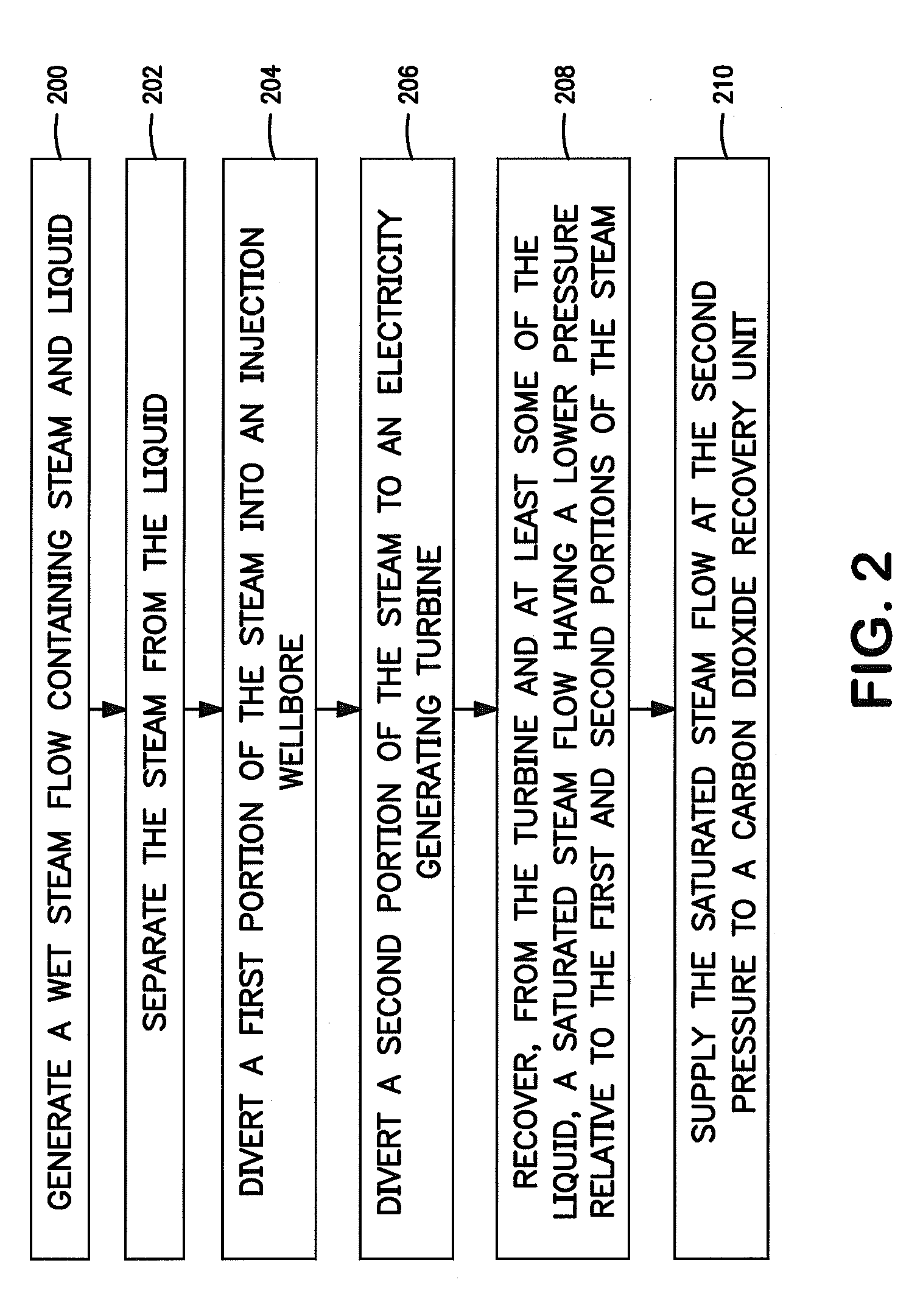
[0014]Embodiments of the invention relate to generating a flow of steam and splitting the flow of steam to enable both its injection into a formation to assist in oil recovery and its introduction into a pathway where the steam is used for generating electricity and capturing carbon dioxide (CO2). At least part of the CO2 that is captured comes from burning of fuel used to generate the steam. Steam assisted gravity drainage (SAGD) requires the steam that is injected to have a higher pressure than the steam that is needed for CO2 capture. Exhaust steam from a steam turbine used to generate the electricity reduces pressure of the steam prior to use of the steam for capturing CO2.

[0015]FIG. 1 shows a production system 100 for integrated steam assisted oil recovery and CO2 capture. The system 100 includes a steam generator such as a once-through steam generator (OTSG) 102 that is supplied with boiler-feed-water 104. The OTSG 102 generates steam by a single-pass of the boiler-feed-water ...


PUM


Abstract

Methods and systems relate to generating a flow of steam and splitting the flow of steam to enable both its injection into a formation to assist in oil recovery and its introduction into a pathway where the steam is used for generating electricity and capturing carbon dioxide (CO2). At least part of the CO2 that is captured comes from burning of fuel used to generate the steam. Steam assisted gravity drainage requires the steam that is injected to have a higher pressure than the steam that is needed for CO2 capture. Exhaust steam from a steam turbine used to generate the electricity reduces pressure of the steam prior to use of the steam for capturing CO2.

Description

CROSS-REFERENCE TO RELATED APPLICATIONS[0001]NoneSTATEMENT REGARDING FEDERALLY SPONSORED RESEARCH OR DEVELOPMENT[0002]NoneFIELD OF THE INVENTION[0003]Embodiments of the invention relate to methods and systems for steam assisted oil recovery and carbon dioxide capture.BACKGROUND OF THE INVENTION[0004]In order to recover oils from certain geologic formations, injection of steam increases mobility of the oil within the formation. An example of such a process is known as steam assisted gravity drainage (SAGD). Oil producers often utilize a once-through steam generator (OTSG) to make the steam by a single-pass of boiler-feed-water through boiler tubes that are heated by gas or oil burners. The OTSG may produce about seventy five percent (75%) quality steam such that output from the OTSG is about 75% vapor and about 25% liquid, by weight percent.[0005]Burning the gas or oil to fuel the burners creates carbon dioxide (CO2), which is a greenhouse gas. Capturing the CO2 facilitates in limiti...

Claims


Application Information

Patent Timeline
IPC IPC(8): E21B43/24
CPCE21B41/0064Y02C10/14E21B43/2406Y02C20/40
Inventor EMBRY, DALE L.LAMONT, DAVID C.SEABA, JAMES P.
Owner CONOCOPHILLIPS CO
Why Eureka
Try Eureka