Ultrasonic treatment chamber for treating hydrogen isotopes

a technology of hydrogen isotopes and treatment chambers, which is applied in the direction of nuclear reactors, greenhouse gas reduction, nuclear engineering, etc., can solve the problems of growing energy requirements around the world, inability to reproduce, and inability to generate power. the method was impractical, and the effect of straining our current energy sources

Inactive Publication Date: 2010-08-19
KIMBERLY-CLARK WORLDWIDE INC
View PDF101 Cites 20 Cited by
  • Summary
  • Abstract
  • Description
  • Claims
  • Application Information

AI Technical Summary

Benefits of technology

[0008]In one aspect, a system for treating hydrogen isotopes generally comprises a treatment chamber comprising an elongate housing having longitudinally opposite ends and an interior space. The housing is generally closed at least one of its longitudinal ends and has at least one inlet port for receiving a carrier liquid and hydrogen gas isotopes into the interior space of the housing and at least one outlet port through which treated liquid is exhausted from the housing following ultrasonic treatment of the carrier liquid and hydrogen gas isotopes, the ultrasonic treatment of which initiates the fusing of the hydrogen gas isotopes within the carrier liquid to form the treated liquid. The outlet port is spaced longitudinally from the inlet port such that liquid flows longitudinally within the interior space of the housing from the inlet port to the outlet port. In one embodiment, the housing includes two separate ports for receiving the carrier liquid and a third port for receiving hydrogen gas isotopes. At least one elongate ultrasonic waveguide assembly extends longitudinally within the interior space of the housing and is operable at a predetermined ultrasonic frequency to ultrasonically energize liquid flowing within the housing.

Problems solved by technology

Growing energy requirements around the world will place a strain on our current energy sources.
One problem with the above attempt is that it was not reproducible.
Specifically, while many other physicists tried recreating the reaction, all found that the acoustic reactor put out less energy than it required and, as such, the method was impractical for generating power.

Method used


Image

  • Ultrasonic treatment chamber for treating hydrogen isotopes
  • Ultrasonic treatment chamber for treating hydrogen isotopes
  • Ultrasonic treatment chamber for treating hydrogen isotopes

Examples


Embodiment Construction

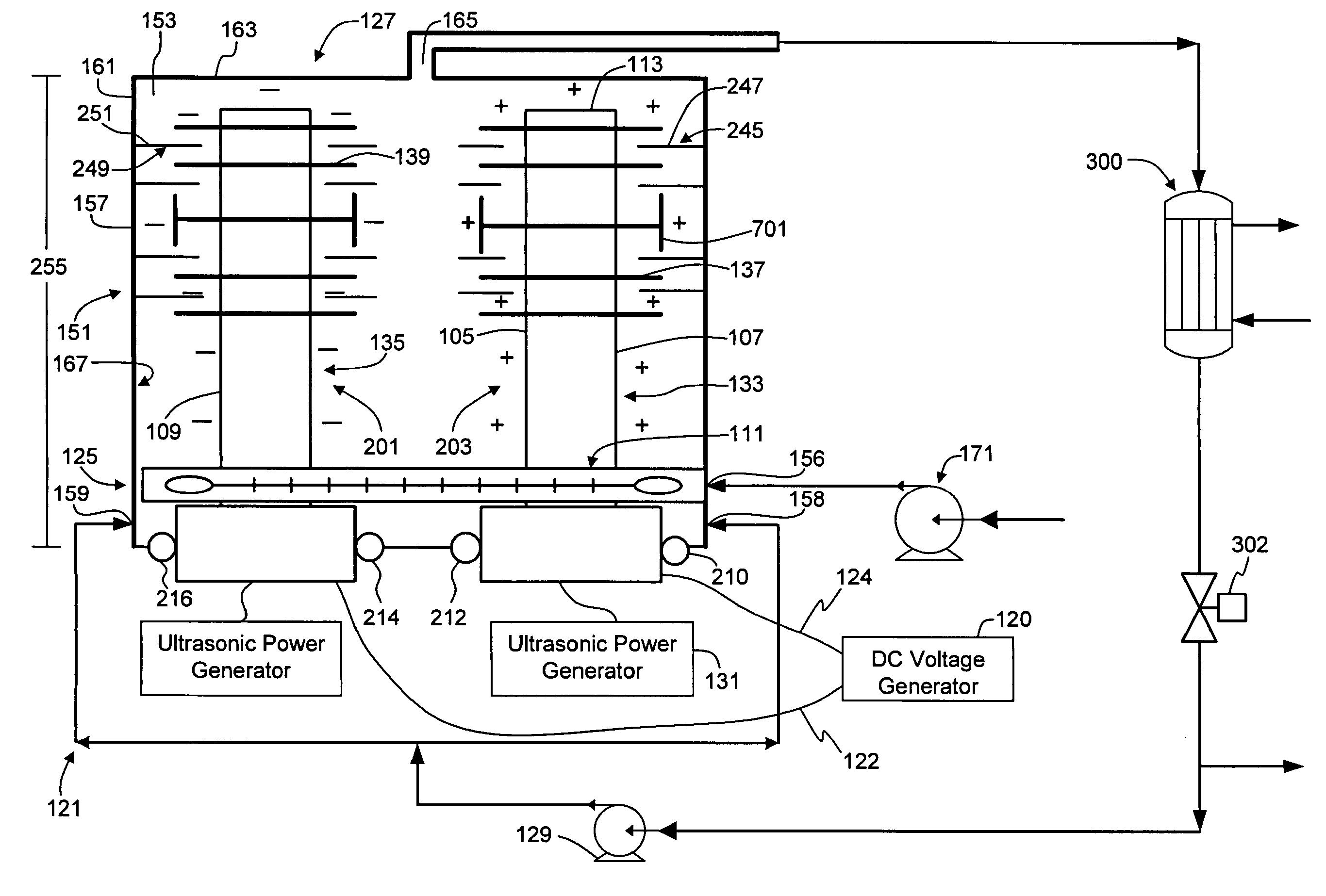
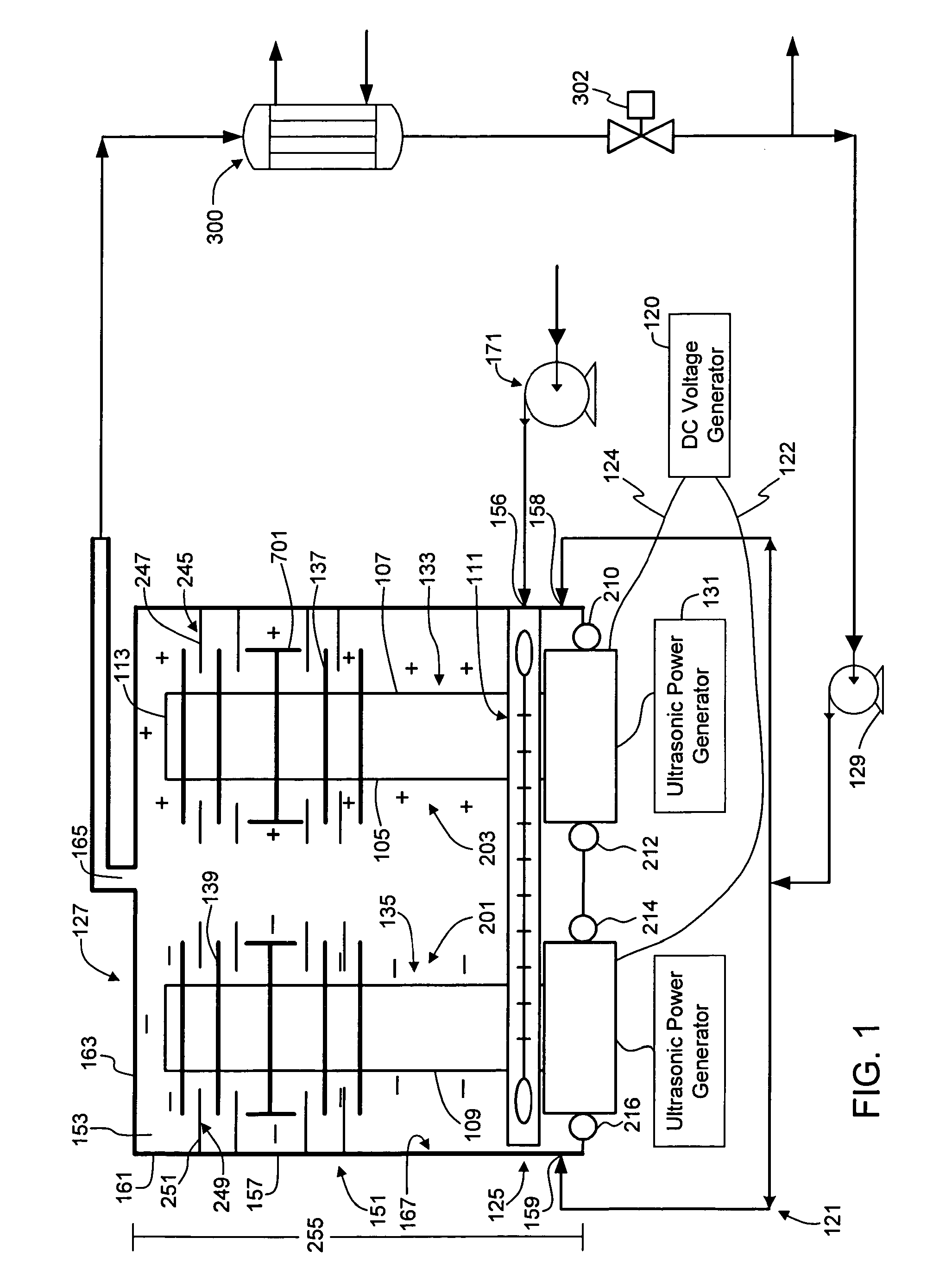
[0018]With particular reference now to FIG. 1, in one embodiment, a thermonuclear fusion system for thermonuclear fusing of hydrogen gas isotopes generally comprises a treatment chamber, generally indicated at 121, that is operable to ultrasonically treat a carrier liquid and hydrogen gas isotopes, thereby creating a cavitation mode that allows for an increase in both temperature and pressure within the housing 151 of the chamber 121 to initiate a thermonuclear fusion reaction. Furthermore, the treatment chamber 151 contains ultrasonic horns 133 and 135 that independently act as electrodes (i.e., an anode and cathode) to attract the respective hydrogen gas isotopes towards the horns' outer surfaces 107 and 109, respectively, through the dipole moment on the gas isotopes, as described more fully below. Under such conditions, there is an increased concentration of hydrogen gas isotopes around the respective electrodes (i.e., outer surfaces of the horns), further initiating thermonucle...


PUM

PropertyMeasurementUnit
inlet temperatureaaaaaaaaaa
pressureaaaaaaaaaa
electrical potentialaaaaaaaaaa

Abstract

A system is disclosed for treating hydrogen isotopes. Specifically, the system includes a treatment chamber that has an elongate housing through which liquid and gas isotopes flow longitudinally from an inlet port to an outlet port thereof. An elongate ultrasonic waveguide assembly extends within the housing and is operable at a predetermined ultrasonic frequency and a predetermined electrical potential to ultrasonically enhance the concentration of dissolved hydrogen gas isotopes within the housing or energize and electrolyze the liquid and gas isotopes within the housing. An elongate ultrasonic horn of the waveguide assembly is disposed at least in part intermediate the inlet and outlet ports, and has a plurality of discrete agitating members in contact with and extending transversely outward from the horn intermediate the inlet and outlet ports in longitudinally spaced relationship with each other.

Description

CROSS-REFERENCE TO RELATED APPLICATION[0001]This application is a continuation of U.S. patent application Ser. No. 11 / 950,943, filed Dec. 5, 2007, which is hereby incorporated by reference in its entirety.FIELD OF DISCLOSURE[0002]The present disclosure relates generally to systems for treating hydrogen isotopes and, more particularly, a system for ultrasonically treating and electrolyzing a flowing carrier liquid and hydrogen gas isotopes.BACKGROUND OF DISCLOSURE[0003]Growing energy requirements around the world will place a strain on our current energy sources. Affordable and plentiful energy is essential towards maintaining healthy industrial societies, as well as raising the standard of living within developing countries. Fusion could provide the energy to meet these requirements, having potential benefits including: a very abundant supply of energy world-wide; an environmentally cleaner source of energy (no air pollution and little if any high level nuclear waste), as well as an...

Claims


Application Information

Patent Timeline
Patent Type & Authority Applications(United States)
IPC IPC(8): C25B1/04C25B9/00
CPCY02E30/18G21B3/00Y02E30/10
Inventor JANSSEN, ROBERT ALLENAHLES, JOHN GLENEHLERT, THOMAS DAVIDMACDONALD, JOHN GAVINMCCRAW, JR., EARL C.MCNICHOLS, PATRICK SEANRASMUSSEN, PAUL WARRENROFFERS, STEVE
Owner KIMBERLY-CLARK WORLDWIDE INC
Why Eureka
Try Eureka