Particle-counting apparatus with pulse shortening

a technology of pulse shortening and counting apparatus, which is applied in the field of particle counting, can solve the problems of large temporal extension, large width of the electric pulse provided by the detector, and maximum detection particle rate, and achieve the effect of high dynamic range and improved counting ra

Inactive Publication Date: 2010-08-19
KONINKLIJKE PHILIPS ELECTRONICS NV
View PDF5 Cites 20 Cited by
  • Summary
  • Abstract
  • Description
  • Claims
  • Application Information

AI Technical Summary

Benefits of technology

[0005]It is an object of the invention to provide a particle-counting system having an improved coun...

Problems solved by technology

In spite of high-speed digital processing equipment, an inhibiting factor in achieving a high dynamic range is the problem that particles captured by a detector provide an electric pulse having a considerable width, i.e. a considerable temporal extension.
Thus, a particle may be captured by the detector when a particle pulse captured earlier is still within its decay time, and, consequently, the particle pulse captured later may not be detected at all and thus has a limit for the maximally detectable particle ra...

Method used


Image

  • Particle-counting apparatus with pulse shortening
  • Particle-counting apparatus with pulse shortening
  • Particle-counting apparatus with pulse shortening

Examples


Embodiment Construction

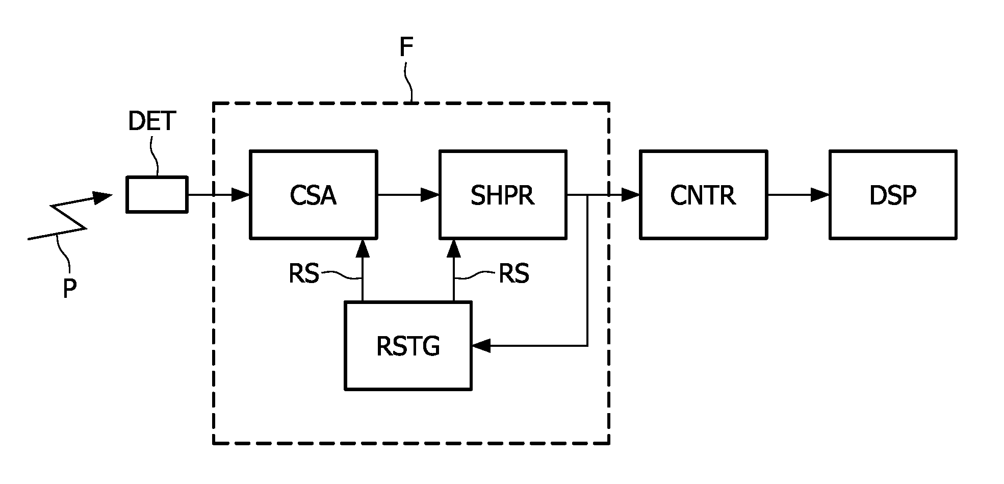
[0036]FIG. 1 illustrates an embodiment of a particle-counting system, such as for use in a medical scanner. A particle or photon P (hereinafter referred to as ‘particle’ only) is captured by a detector DET. The detector generates an electric signal in response to the captured particle P, and this signal is applied to a particle-counting front-end F. The front-end F includes a charge-sensitive amplifier CSA that receives the electric signal from the detector DET. The charge-sensitive amplifier CSA has at least one integrator with a time constant associated therewith, such that the charge-sensitive amplifier CSA has a well-defined rise time and decay time. A shaper circuit SHPR receives the amplified signal from the charge-sensitive amplifier and generates a shaped signal in response thereto. The shaper SHPR also includes an integrator with a time constant associated therewith and may further include a switchable RC network with another time constant associated therewith. The shaped s...


PUM


Abstract

A particle-counting apparatus is described, which reduces a resulting width of pulses when a charge pulse is received from a particle detector, thereby reducing pile-up problems with pulses. Pulse shortening is obtained by resetting the pulse shortly after it exceeds its peak level at the apparatus output. The apparatus includes a charge-sensitive amplifier and a shaper which generates an output for subsequent discrimination circuits. A reset generator monitors the shaper output and generates a reset signal to the shaper when a peak has been detected.

Description

FIELD OF THE INVENTION[0001]The invention relates to the field of particle counting, such as photon counting. More specifically, the invention relates to the field of high-rate photon-counting systems and their control systems, such as for use in e.g. Computer Tomography X-ray Imaging.BACKGROUND OF THE INVENTION[0002]Particle or photon counting or particle-counting techniques are well-known, e.g. in nuclear physics, astronomy, medical imaging, security, etc. These techniques are usable for detection and measurement of high-energy photons or particles of X-rays, Gamma-rays and ionized particles, etc. A detection system based on detector devices and dedicated readout circuits is used to amplify the photocurrent or photovoltage of the detectors, shape them, and make them ready for discrimination by analog-to-digital converters, or by comparing the pulse amplitude with known threshold levels.[0003]Within high-quality image capturing, such as in medical imaging by computer tomography, a ...

Claims


Application Information

Patent Timeline
IPC IPC(8): G01T1/18
CPCG01T1/171
Inventor MARKS, AVIVLIRAN, TUVIA
Owner KONINKLIJKE PHILIPS ELECTRONICS NV
Why Eureka
Try Eureka