Speaker device

a speaker device and speaker technology, applied in the direction of transducer details, transducer diaphragms, electrical transducers, etc., can solve the problems of difficult to reduce the size and profile of the speaker device, the ring-shaped magnet of the outer magnet type magnetic circuit has a relatively large weight, and the height of the cone speaker is difficult to reduce. , to achieve the effect of high quality

Inactive Publication Date: 2010-08-19
PIONEER CORP +1
View PDF10 Cites 19 Cited by
  • Summary
  • Abstract
  • Description
  • Claims
  • Application Information

AI Technical Summary

Benefits of technology

The present invention aims to create a speaker that is smaller, lighter, and flatter than previous versions. Additionally, it aims to produce high-quality sound.

Problems solved by technology

The technical problem addressed in this patent text is the difficulty in reducing the size and profile of speaker devices that use an outer magnet type magnetic circuit, due to the relatively large weight of the ring-shaped magnet and the difficulty in miniaturizing the magnet. This makes it difficult to attach speaker devices to narrow spaces such as automobile doors or electronic displays. There is a need for a speaker device that can be reduced in size and profile without compromising the quality of the reproduced sound.

Method used


Image

  • Speaker device
  • Speaker device
  • Speaker device

Examples


Embodiment Construction

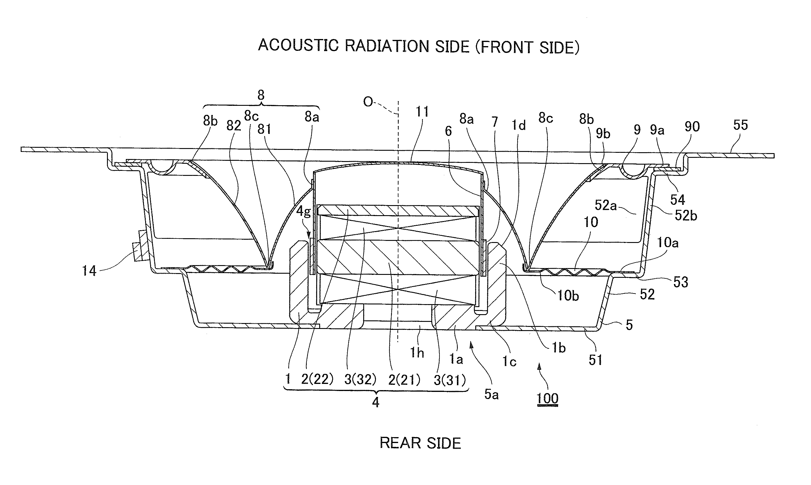
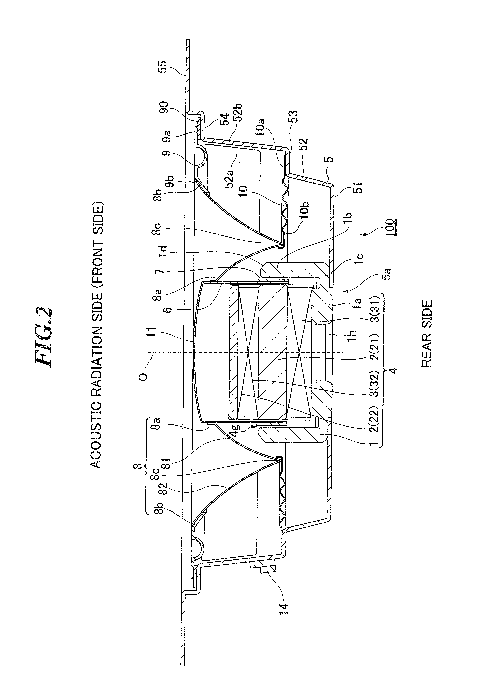
[0029]A speaker device according to an embodiment of the present invention includes: a frame; a diaphragm having an inner rim connected to a voice coil bobbin and an outer rim connected to the frame through an edge, the diaphragm being shaped so that a peak portion thereof is formed between the inner rim and the outer rim which are positioned at an acoustic radiation side in comparison with the peak portion; a damper having an outer rim connected to the frame on the one hand and an inner rim supporting the peak portion of the diaphragm on the other hand; and an inner magnet type magnetic circuit for driving a voice coil arranged on the voice coil bobbin.

[0030]In the speaker device of the above configuration, the inner magnet type magnetic circuit drives the diaphragm of the foregoing shape through the voice coil and the voice coil bobbin. As compared to conventional speaker devices in which the diaphragm is driven by using, for example, an outer magnet type magnetic circuit, the spe...


PUM


Abstract

Objects are to make a speaker device smaller than heretofore in size, in profile, and in weight, and to reproduce sound in high quality. The speaker device includes: a diaphragm which has an inner rim connected to a voice coil bobbin and an outer rim connected to a frame through an edge, and is shaped so that a peak portion is formed between the inner rim and the outer rim, which are positioned at an acoustic radiation side in comparison with the peak portion; and an inner magnet type magnetic circuit for driving a voice coil which is arranged on the voice coil bobbin connected to the inner rim of the diaphragm.

Description


Claims


Application Information

Patent Timeline
Owner PIONEER CORP
Why Eureka
Try Eureka