Brake control apparatus and control method for the brake control apparatus

a technology of brake control apparatus and control method, which is applied in the direction of braking system, instruments, analogue processes for specific applications, etc., can solve problems such as malfunctions in the first pressure sensor, and achieve the effect of suppressing the occurrence of malfunctions

Active Publication Date: 2010-08-19
TOYOTA JIDOSHA KK
View PDF9 Cites 58 Cited by
  • Summary
  • Abstract
  • Description
  • Claims
  • Application Information

AI Technical Summary

Benefits of technology

[0009]The invention provides a brake control apparatus that protects a pressure sensor from a pressure increase to suppress occurrence of a malfunction in the pressure sensor.

Problems solved by technology

Therefore, for example, if the hydraulic fluid is pressurized in the manual hydraulic pressure source in accordance with the operation performed by the driver and an excessive pressure that exceeds a withstanding pressure limit for the first pressure sensor is generated in the first hydraulic circuit, a malfunction may occur in the first pressure sensor.

Method used


Image

  • Brake control apparatus and control method for the brake control apparatus
  • Brake control apparatus and control method for the brake control apparatus
  • Brake control apparatus and control method for the brake control apparatus

Examples


first embodiment

OF THE INVENTION

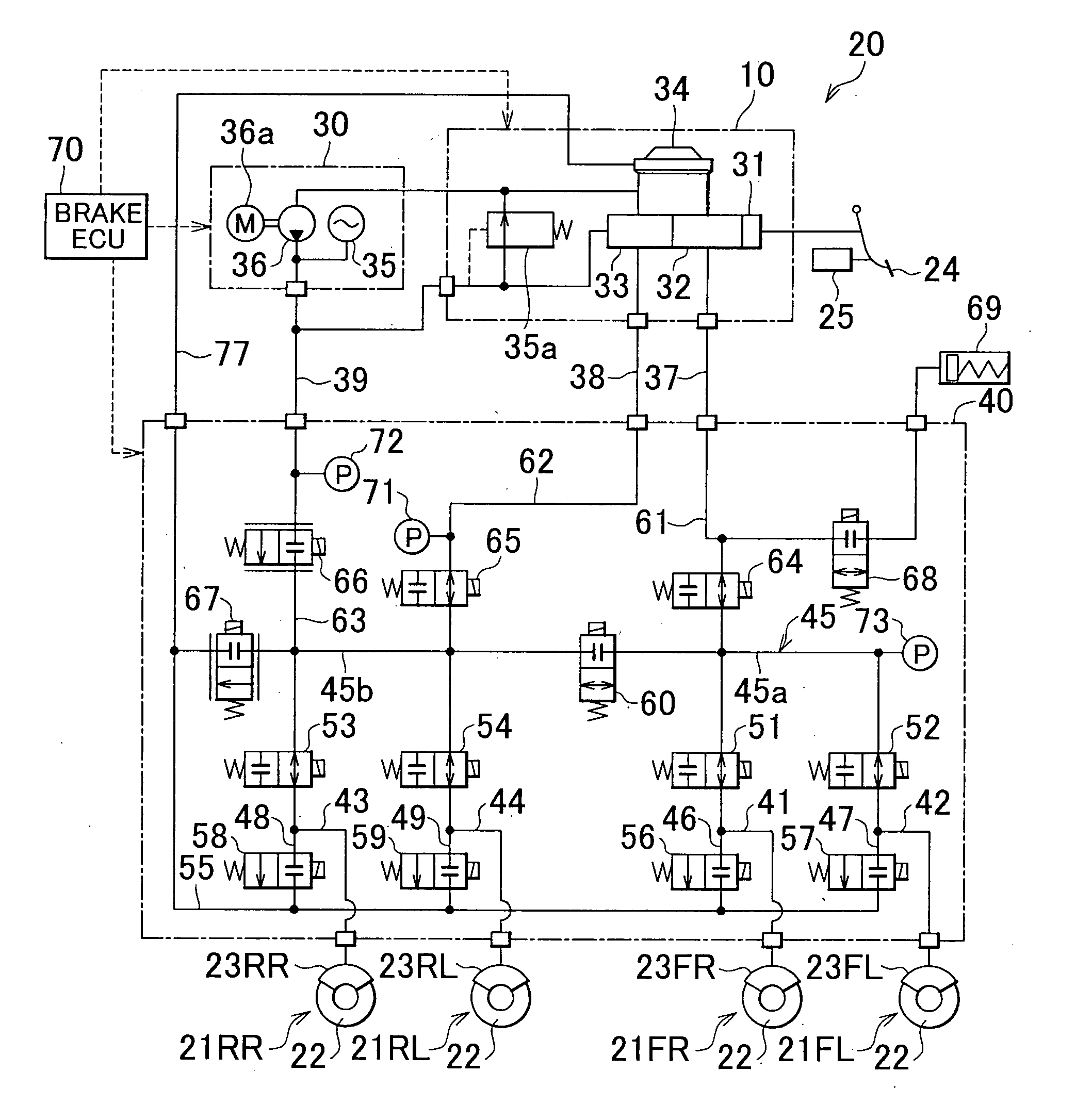
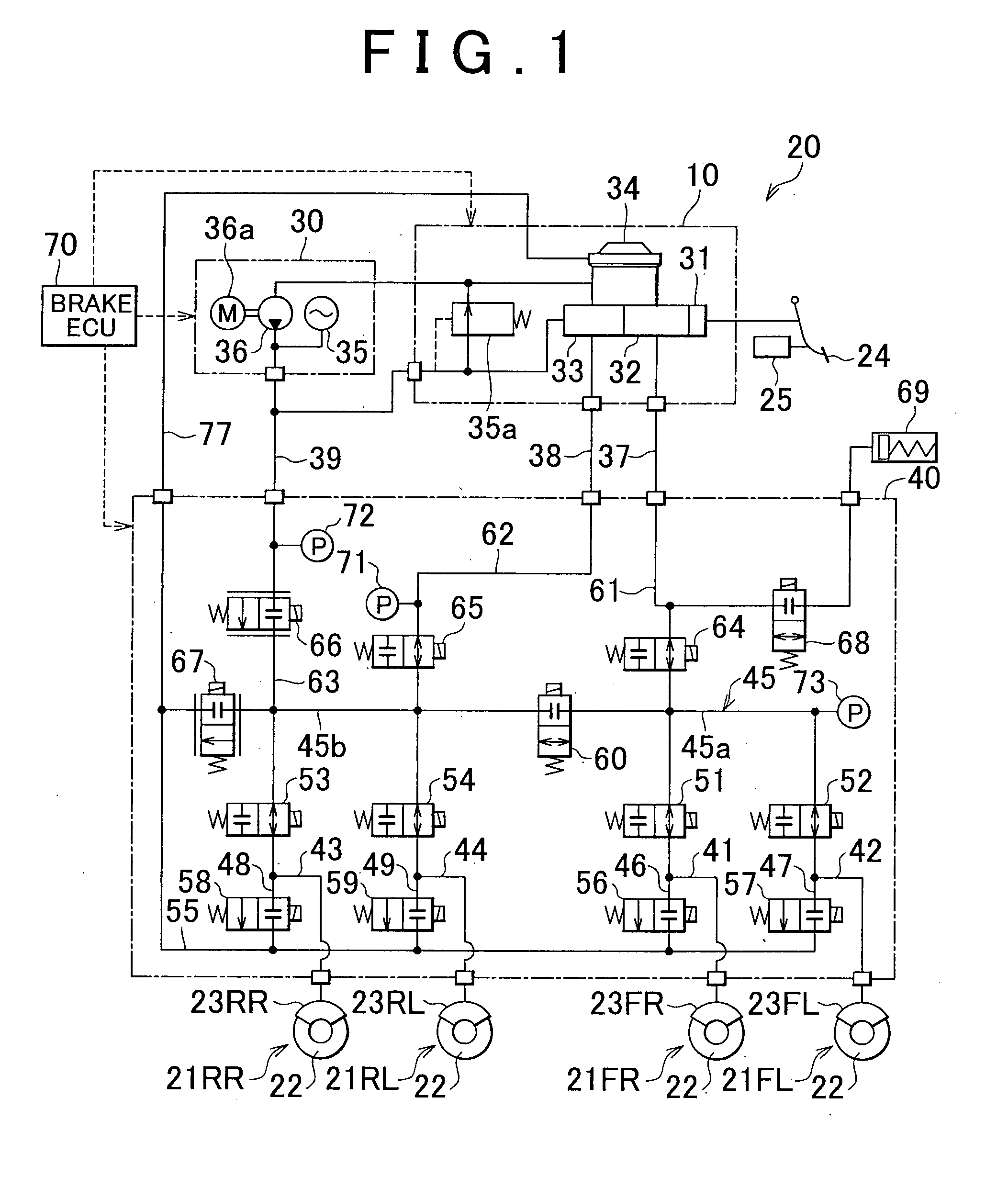
[0033]FIG. 1 is a system diagram showing a brake control apparatus 20 according to a first embodiment of the invention. The brake control apparatus 20 shown in FIG. 1 forms an electronically-controlled brake system for a vehicle, and controls braking forces that are applied to four wheels of a vehicle. The brake control apparatus 20 according to the first embodiment of the invention is mounted on, for example, a hybrid vehicle provided with an electric motor and an internal combustion engine that serve as drive power sources. In a hybrid vehicle, braking force may be applied to the vehicle through a regenerative braking operation in which kinetic energy of the vehicle is converted into electric energy and stored or a hydraulic pressure braking operation executed by the brake control apparatus 20. In the vehicle in the first embodiment of the invention, it is also possible to execute a cooperative braking control to generate desired braking force through combined exec...

second embodiment

OF THE INVENTION

[0114]In a brake control apparatus 20 according to a second embodiment of the invention, if the pressure, which is detected by the control pressure sensor 73 while the partition valve 60 is closed, is equal to or higher than the predetermined value, the partition valve 60 and the pressure-decreasing linear control valve 67 are opened to suppress an increase in the pressure in the first passage 45a to which the control pressure sensor 73 is connected. FIG. 8 is a flowchart describing a control routine for protecting the control pressure sensor when the pressure is increased in the hydro-booster mode according to the second embodiment of the invention. Mainly, the features that differ from those in the first embodiment of the invention will be described below, and description concerning the features that are common to the first embodiment and the second embodiment of the invention will not be provided below.

[0115]The brake ECU 70 receives the detection value Pfr from t...

third embodiment

OF THE INVENTION

[0120]In a brake control apparatus 20 according to a third embodiment of the invention, if the pressure that is detected by the control pressure sensor 73 while the partition valve 60 is closed is equal to or higher than a predetermined value, the ABS pressure-decreasing valve 56 is opened to suppress an increase in the pressure in the first passage 45a to which the control pressure sensor 73 is connected. FIG. 9 is a flowchart describing a control routine for protecting the control pressure sensor when the pressure is increased in the hydro-booster mode according to the third embodiment of the invention. Mainly, the features that differ from those in the first and second embodiments of the invention will be described below, and description concerning the features that are common to the third embodiment and the first and second embodiments will not be provided below.

[0121]While the braking operation is performed in the hydro-booster mode, the brake ECU 70 receives th...


PUM


Abstract

In a brake control apparatus that controls braking forces which are applied to wheels based on the pressure of the hydraulic fluid, when the pressure detected by a control pressure sensor (73) is equal to or higher than a predetermined value while a partition valve (60) is closed, a master cut valve (64) is closed to suppress an increase in the pressure in a first passage (45) in a first hydraulic circuit (37), to which the control pressure sensor (73) is connected. Alternatively, the control pressure sensor (73) is protected against overpressure by opening the outlet valve (56,57) or the pressure-decreasing valve (67).

Description

BACKGROUND OF THE INVENTION[0001]1. Field of the Invention[0002]The invention relates generally to a brake control apparatus that controls braking forces that are applied to wheels of a vehicle, and, more specifically to a technology for protecting a pressure sensor included in the brake control apparatus.[0003]2. Description of the Related Art[0004]There is a hydraulic control apparatus that generates a hydraulic pressure corresponding to an operation amount of a brake pedal in a hydraulic circuit, and supplies the hydraulic pressure generated in the hydraulic circuit to wheel cylinders, thereby applying braking forces to wheels of a vehicle. Also, there is a hydraulic control apparatus that is provided with an actuator which includes a pair of electromagnetically-controlled valves that are used to increase or decrease the pressures in wheel cylinders fitted to respective wheels, and an electronic control unit that controls the actuator. With the hydraulic control apparatus, an amo...

Claims


Application Information

Patent Timeline
Patent Type & Authority Applications(United States)
IPC IPC(8): B60T13/00G06F19/00B60T8/17B60T17/18
CPCB60T8/4081
Inventor NAKATA, DAISUKEOKANO, TAKAHIRO
Owner TOYOTA JIDOSHA KK
Why Eureka
Try Eureka