Thrust reverser configuration for a short fan duct

a technology of fan duct and thrust reverser, which is applied in the direction of machines/engines, climate sustainability, sustainable transportation, etc., can solve the problems of affecting the operating stability of the turbofan jet engine, affecting and reducing the performance of the thrust reverser

Active Publication Date: 2010-08-26
SPIRIT AEROSYSTEMS
View PDF27 Cites 49 Cited by
  • Summary
  • Abstract
  • Description
  • Claims
  • Application Information

AI Technical Summary

Benefits of technology

[0009]The torque beam may be positioned within the nacelle to provide structural support to other members of t...

Problems solved by technology

Simply reducing the size of the components to fit within a shortened fan duct length leads to diminished or alter...

Method used


Image

  • Thrust reverser configuration for a short fan duct
  • Thrust reverser configuration for a short fan duct
  • Thrust reverser configuration for a short fan duct

Examples


Embodiment Construction

[0034]The following detailed description of the invention references the accompanying drawings that illustrate specific embodiments in which the invention can be practiced. The embodiments are intended to describe aspects of the invention in sufficient detail to enable those skilled in the art to practice the invention. Other embodiments can be utilized and changes can be made without departing from the scope of the present invention. The following detailed description is, therefore, not to be taken in a limiting sense. The scope of the present invention is defined only by the appended claims, along with the full scope of equivalents to which such claims are entitled.

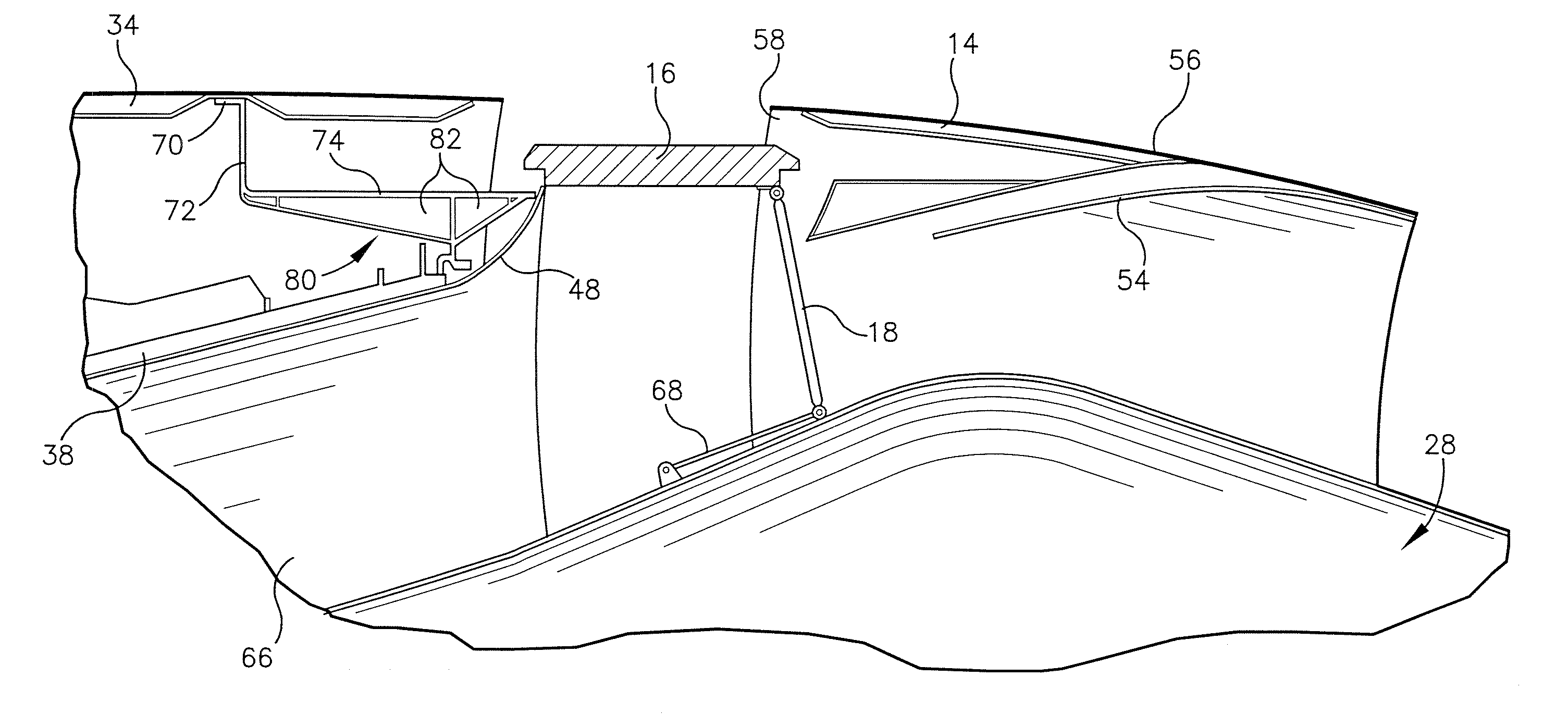
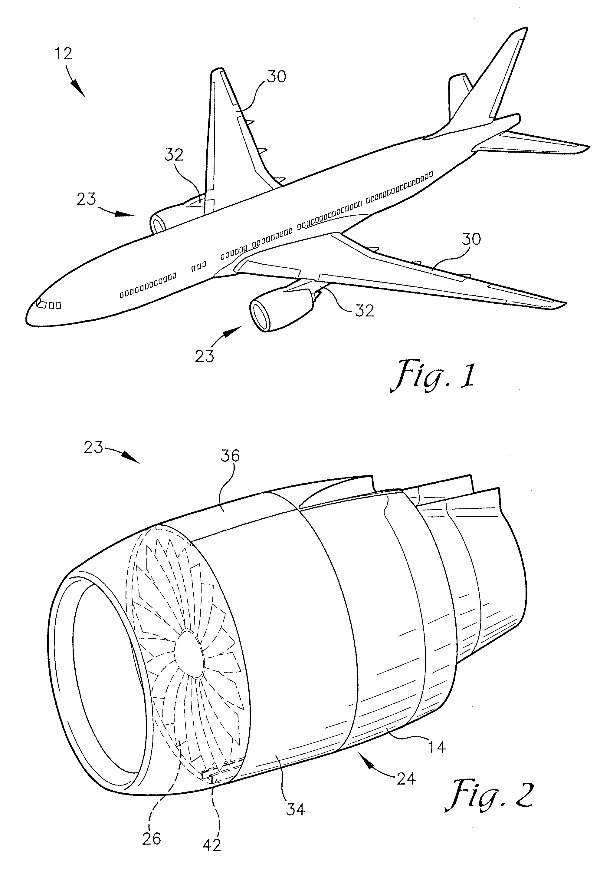
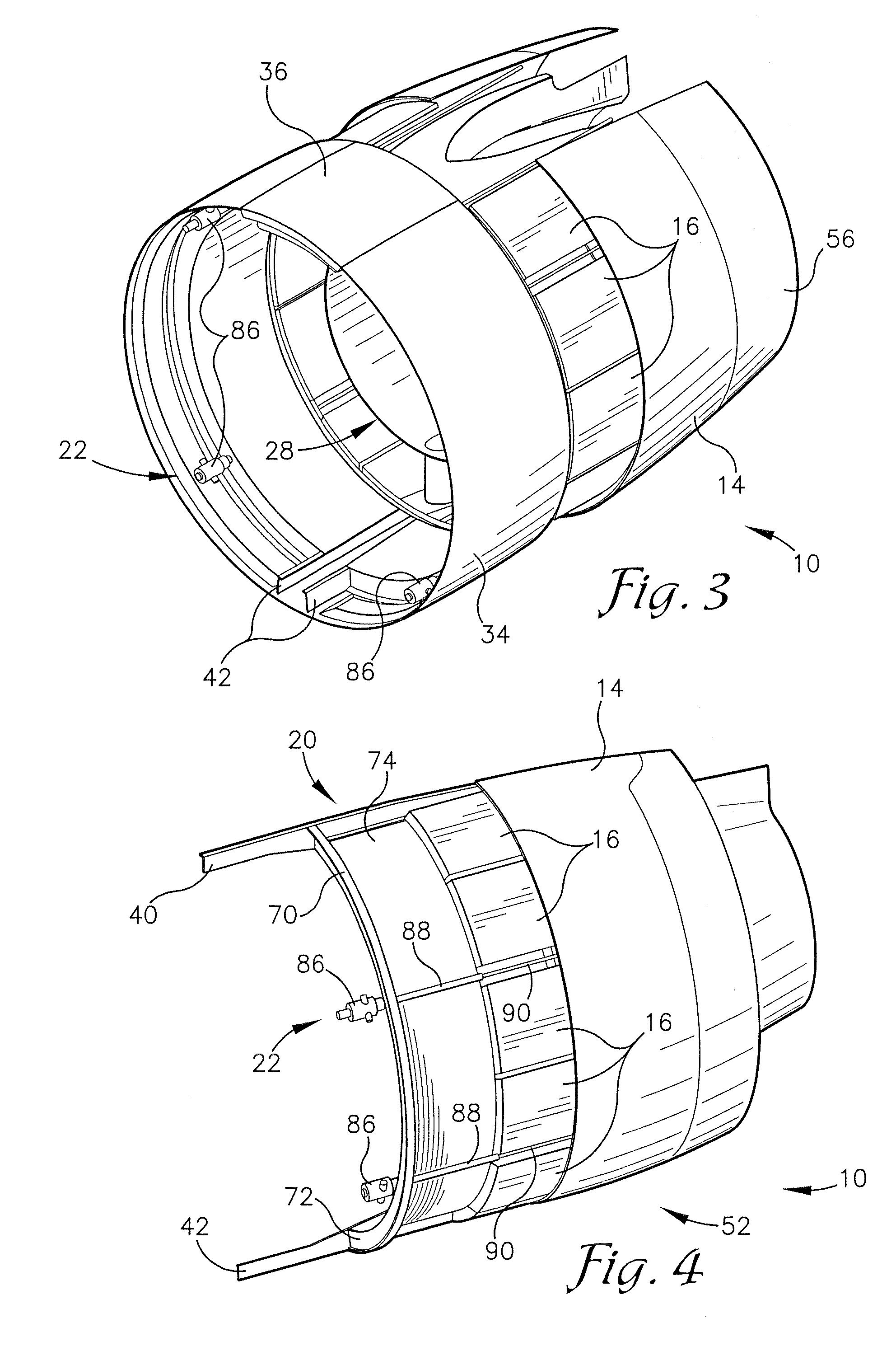
[0035]A thrust reverser 10 constructed in accordance with various embodiments of the current invention is shown in FIGS. 1-8. The thrust reverser 10, when deployed, provides reverse thrust for an aircraft 12 while the aircraft 12 is landing. However, during takeoff, and when in flight, the thrust reverser 10 is stowed t...


PUM


Abstract

A thrust reverser comprises a translating sleeve, a torque beam, a plurality of cascades, a plurality of blocker doors, and a plurality of actuators. The translating sleeve is positioned at the rear of an aircraft nacelle and is translated rearward during thrust reverser deployment. The torque beam is positioned within the nacelle and configured to prevent airflow into the nacelle during thrust reverser deployment. The plurality of cascades are positioned around the circumference of the torque beam during thrust reverser stowage and are translated rearward during thrust reverser deployment. The plurality of blocker doors are positioned in alignment with the plurality of cascades and direct airflow through the plurality of cascades during thrust reverser deployment. The plurality of actuators are coupled to the forward edge of the sleeve and configured to translate the sleeve rearward during thrust reverser deployment.

Description

BACKGROUND OF THE INVENTION[0001]1. Field of the Invention[0002]Embodiments of the present invention relate to aircraft engine thrust reversers. More particularly, embodiments of the present invention relate to cascade thrust reversers for use with an aircraft engine with a short fan duct.[0003]2. Description of the Related Art[0004]Many commercial jet aircraft include turbofan jet engines as the main source of propulsion. This type of engine includes a nacelle that surrounds an intake fan and a turbine engine. The intake fan brings air into the engine and a portion of the airstream enters the turbine engine, which is combusted to provide thrust. The rest of the airstream bypasses the turbine engine and flows through a fan duct that surrounds the turbine engine within the nacelle. The airstream exiting the fan duct also provides thrust.[0005]The engine may also include a thrust reverser to provide reverse thrust during landing in order to slow the aircraft when the aircraft is on th...

Claims


Application Information

Patent Timeline
IPC IPC(8): F02K3/02
CPCF02K1/32F02K1/64Y02T50/671F02K1/763F02K1/766F02K1/72Y02T50/60
Inventor WEST, RANDALL R.SCHAEFER, HENRY A.
Owner SPIRIT AEROSYSTEMS
Why Eureka
Try Eureka