
Method for inserting predetermined breaking points in a ring-shaped holding- and sealing band of a sabot cage projectile and a work tool for carrying out the method

a technology of sabot cage and sealing band, which is applied in the direction of ammunition projectiles, weapons components, hollow objects, etc., can solve the problems of high cost associated with milling for insertion of predetermined breaking points in sealing band, and the expense of milling process is also relatively time- and cost-intensiv

Inactive Publication Date: 2010-08-26
RHEINMETALL WAFFE MUNITION GMBH
View PDF14 Cites 16 Cited by
  • Summary
  • Abstract
  • Description
  • Claims
  • Application Information

AI Technical Summary

Benefits of technology

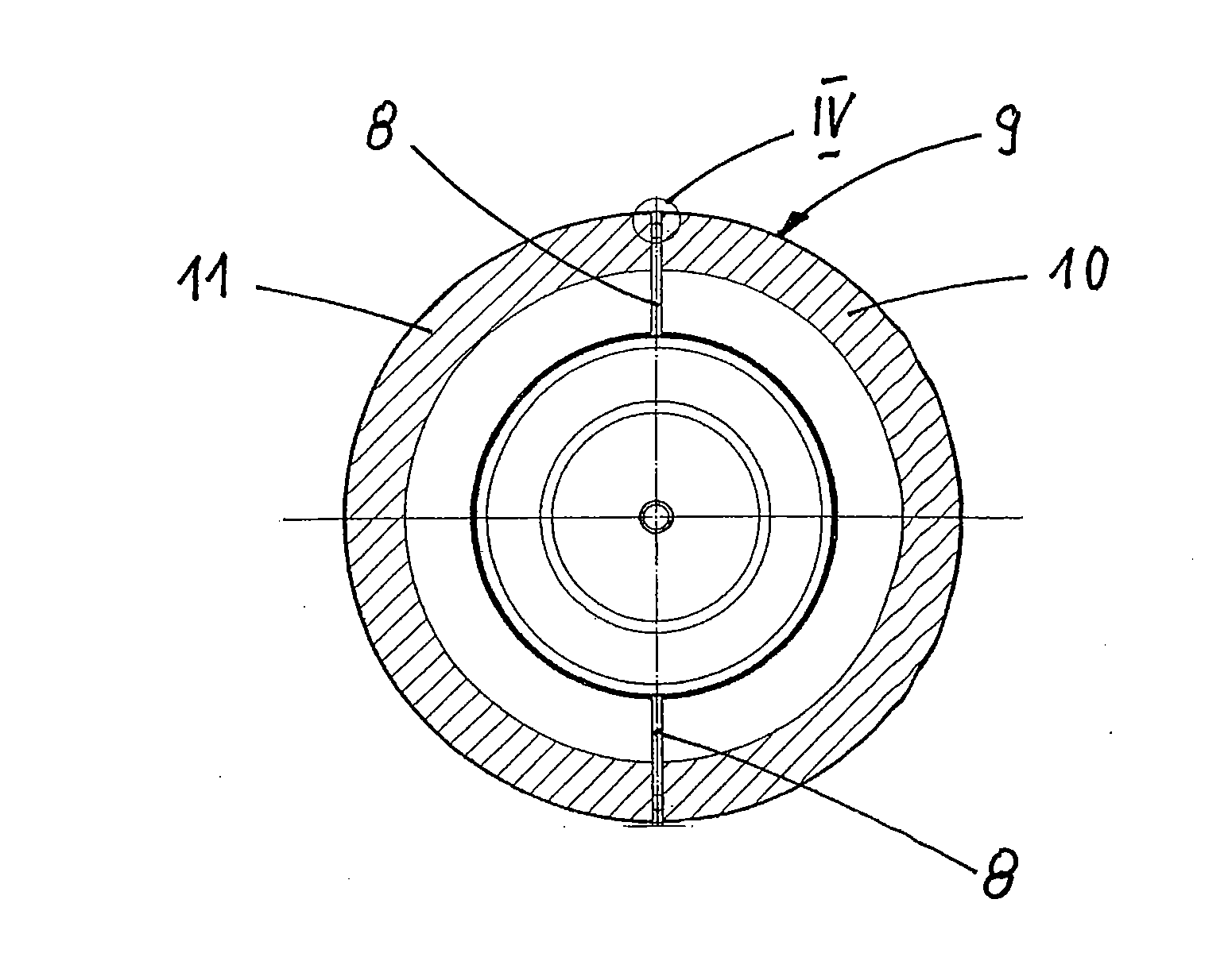
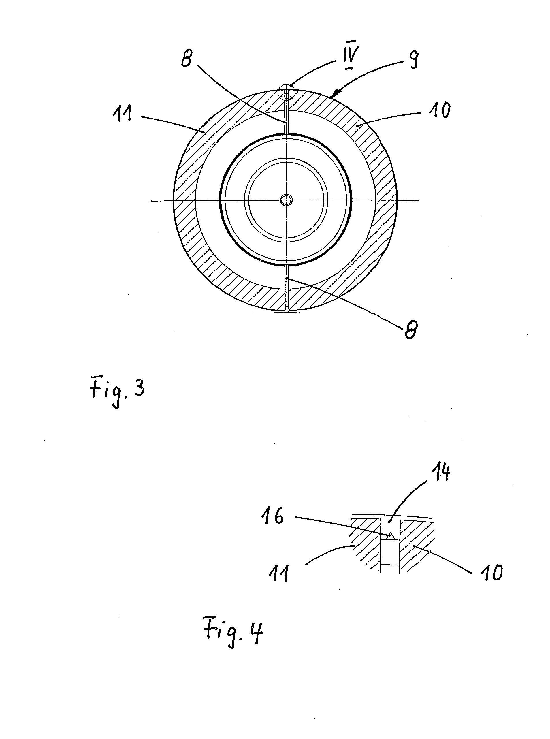
[0011]Thus, the invention is based essentially on the concept that after the mounting of the holding- and sealing band on the receptacle device, but before the installation of the guiding cage, in the area of the holding- and sealing band covering the longitudinal slits of the receptacle device notch-shaped predetermined breaking points are inserted into the holding- and sealing band from the inside with the aid of blade-shaped tools, wherein the longitudinal slits of the segmented receptacle device are used for the lateral guiding of the blade-shaped tools. Through the matching of the blade-shaped tools to the longitudinal slits of the receptacle device, the notching in the holding- and sealing band is always positioned with sufficient precision. Moreover, through the use of a notching on the inside in the area of the longitudinal slits of the holding- and sealing band, the notch action is strengthened through the pressing together of the holding- and sealing band effected through the barrel wall at the firing of the corresponding projectile arrangement. The insertion of the notch-shaped predetermined breaking points in the holding- and sealing band arises preferably through the press seating of the holding band to the receptacle device, but can also be created through an axial displacement of the blade-shaped tools.

Problems solved by technology

The disadvantage with these known sabot cage projectiles is the relatively high costs associated with the milling for insertion of the predetermined breaking points in the sealing band.
However, the expense for the milling process would also be relatively time- and cost-intensive in this case.

Method used


Image

  • Method for inserting predetermined breaking points in a ring-shaped holding- and sealing band of a sabot cage projectile and a work tool for carrying out the method
  • Method for inserting predetermined breaking points in a ring-shaped holding- and sealing band of a sabot cage projectile and a work tool for carrying out the method
  • Method for inserting predetermined breaking points in a ring-shaped holding- and sealing band of a sabot cage projectile and a work tool for carrying out the method

Examples


Embodiment Construction

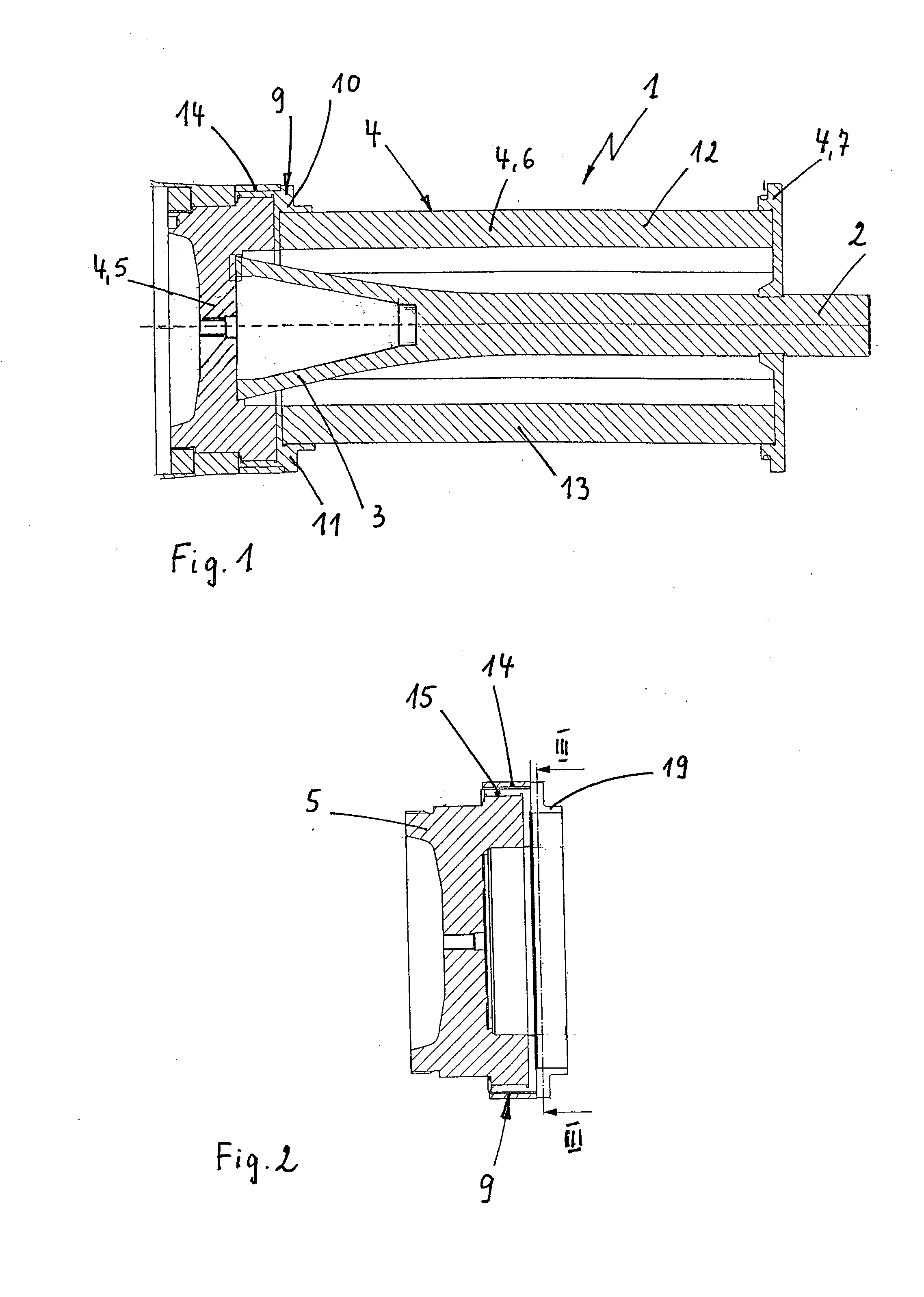
[0023]In FIG. 1, 1 designates a large-caliber practice projectile embodied as a sabot cage projectile (e.g. a 120 mm practice projectile to be shot from a tank cannon), wherein the projectile includes a sub-caliber projectile body 2 with a cone control unit 3 and an impact sabot cage 4. The impact sabot cage 4 comprises essentially a propelling element 5 (also called a pusher plate) acting on the projectile body 2 at the rear, a cylinder-shaped guiding cage 6 segmented through two longitudinal slits lying opposite one another is adjacent at the front to the propelling element 5, and a segmented support wall 7 arranged in the front area of the guiding cage 6, extending radially inwards, and holding the projectile body 2.

[0024]The connection between the guiding cage 6 and the propelling element 5 takes place with the aid of a receptacle device 9, likewise segmented through two longitudinal slits 8 lying opposite one another, wherein the receptacle device is connected to the propelling...


PUM


Abstract

A method and work tool for inserting predetermined breaking points in a ring-shaped holding- and sealing band of a sabot cage projectile with an impact sabot cage are provided, wherein the band is arranged on a partial area of a receptacle device segmented through at least two longitudinal slits. The receptacle device connects the propelling element to the guiding cage of the impact sabot cage, and the guiding cage is segmented through at least two longitudinal slits. After mounting the band on the receptacle device, but before installation of the guiding cage in the area of the holding- and sealing band covering the longitudinal slits of the receptacle device, notch-shaped predetermined breaking points are inserted in the holding- and sealing band from inside of the band with the aid of a work tool, wherein longitudinal slits of the receptacle device are used for lateral guiding of the work tool.

Description

[0001]This application claims priority from German Patent Application No. DE 10 2009 009 772.4, filed Feb. 20, 2009, the entire disclosure of which is incorporated herein by reference.FIELD OF THE INVENTION[0002]The invention relates to a method for inserting predetermined breaking points in a ring-shaped holding- and sealing band of a sabot cage projectile with an impact sabot cage, wherein the holding- and sealing band is arranged on a partial area of a receptacle device segmented through at least two longitudinal slits, wherein the receptacle device connects the propelling element to the guiding cage of the impact sabot cage projectile, and the guiding cage is segmented through at least two longitudinal slits. The invention further relates to a work tool for carrying out the method.BACKGROUND OF THE INVENTION[0003]In known large-caliber sabot cage projectiles, which respectively include a sub-caliber penetrator and a center sabot cage segmented through longitudinal slits (i.e., a...

Claims


Application Information

Patent Timeline
IPC IPC(8): F42B33/00
CPCF42B14/02F42B14/067F42B14/064
Inventor HEITMANN, THOMAS
Owner RHEINMETALL WAFFE MUNITION GMBH
Learn More