

Phase-shift diffraction/interference measuring instrument and method for detecting three-dimensional shape of microsphere
A technology of three-dimensional shape and interferometric measurement, which is applied in the direction of measuring devices, instruments, and optical devices, etc. It can solve the problems of difficulty in manufacturing an ideal spherical surface of the reference surface, and the small detection range of a single measurement.
- Summary
- Abstract
- Description
- Claims
- Application Information
AI Technical Summary
Problems solved by technology
Method used
Image

Examples
specific Embodiment approach 1
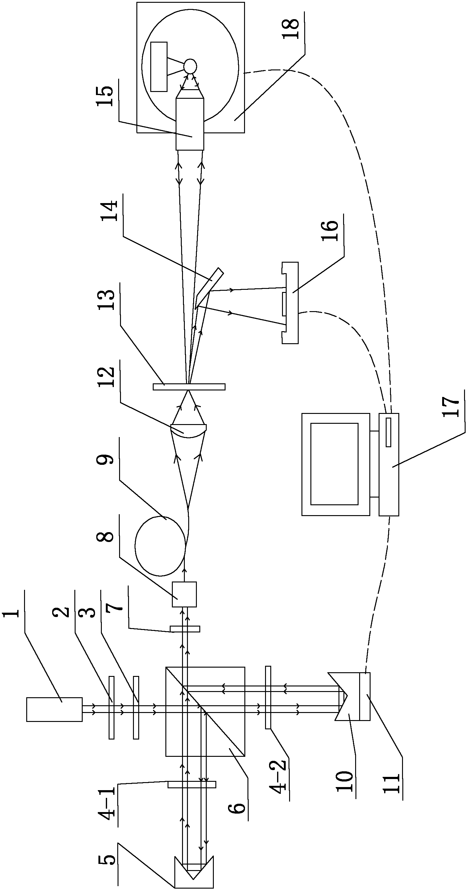
[0039] Specific implementation mode one: the following combination figure 1 Describe this embodiment, the phase-shifting diffraction interferometer for detecting the three-dimensional shape of a microsphere described in this embodiment, it includes a short coherent laser 1, a half-wave plate 2, a polarizer 3, a first four One-quarter wave plate 4-1, second quarter-wave plate 4-2, right-angle retardation prism 5, polarizing beam splitter 6, analyzer 7, fiber coupler 8, single-mode single-core fiber 9, right-angle shift Phase prism 10, converging lens 12, pinhole sheet 13, knife-edge mirror 14, microscope objective lens 15, large-size CCD 16 and computer 17,
[0040] The outgoing laser beam of the short coherent laser 1 passes through the half-wave plate 2 and the polarizer 3 to form polarized light. A wave plate 4-2 is incident to the right-angle phase-shifting prism 10, and the light beam reflected by the right-angle phase-shifting prism 10 is incident on the second quarter-w...
specific Embodiment approach 2
[0049] Specific implementation mode two: the following combination figure 1 This embodiment is described. This embodiment is a further description of Embodiment 1. It also includes a vacuum adsorption two-dimensional turntable 18. The vacuum adsorption two-dimensional turntable 18 is used to place the measured microspheres. The turntable control signal input end is connected to the two-dimensional turntable control signal output end of the computer 17 .
[0050] The rotation center of the vacuum adsorption two-dimensional turntable 18 is located on the main optical axis of the microscope objective lens 15 .
specific Embodiment approach 3
[0051] Specific implementation mode three: the following combination figure 1 Describe this embodiment mode, this embodiment mode is the further explanation to embodiment one or two, it also comprises micro-displacement driving platform 11, the mesa of described micro-displacement driving platform 11 rigidly connects right-angle phase-shifting prism 10, micro-displacement driving platform 11 The displacement control signal input end of the computer 17 is connected to the displacement control signal output end.
[0052] The right-angle phase-shifting prism 10 is rigidly connected to the table top of the micro-displacement driving platform 11, and through the driving of the micro-displacement driving platform 11, the right-angle phase-shifting prism 10 can move parallel to the optical axis direction of its incident light beam.
[0053] The micro-displacement driving platform 11 in this embodiment can be a special phase-shifting platform of model S-303 from PI Company of Germany,...
PUM
| Property | Measurement | Unit |
|---|---|---|
| Diameter | aaaaa | aaaaa |
| Wavelength | aaaaa | aaaaa |
| Coherence length | aaaaa | aaaaa |
Abstract
Description
Claims
Application Information