Microdroplet Generation Apparatus

Inactive Publication Date: 2010-08-26
HEALTH & LIFE CO LTD
View PDF9 Cites 11 Cited by
  • Summary
  • Abstract
  • Description
  • Claims
  • Application Information

AI Technical Summary

Benefits of technology

[0006]The primary objective of the present invention is to provide a microdroplet generation apparatus, which applies to a sprayer, wherein the oscilla

Problems solved by technology

Thus, there is a problem of vibration conduction efficiency in addition to the problem of joining multiple materials.
When the oscillation plate pas

Method used


Image

  • Microdroplet Generation Apparatus
  • Microdroplet Generation Apparatus
  • Microdroplet Generation Apparatus

Examples


first embodiment

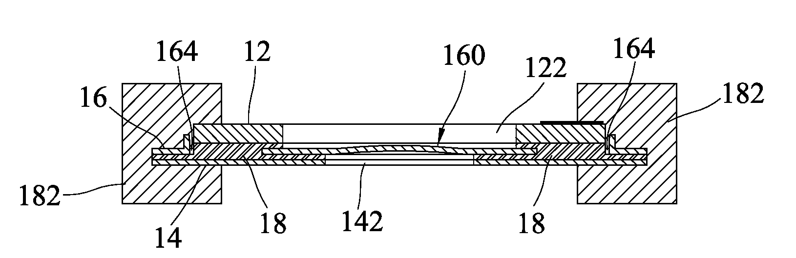
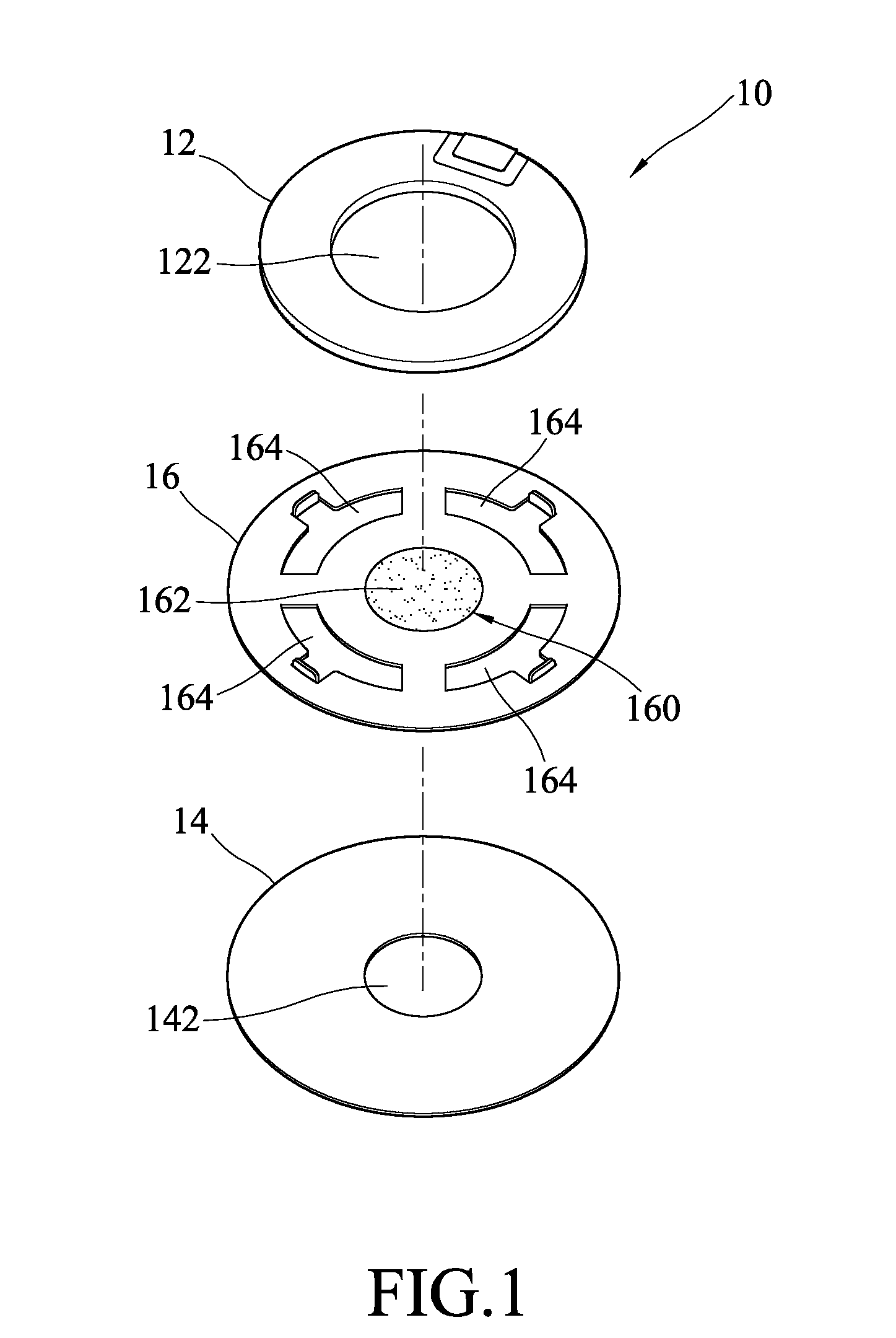
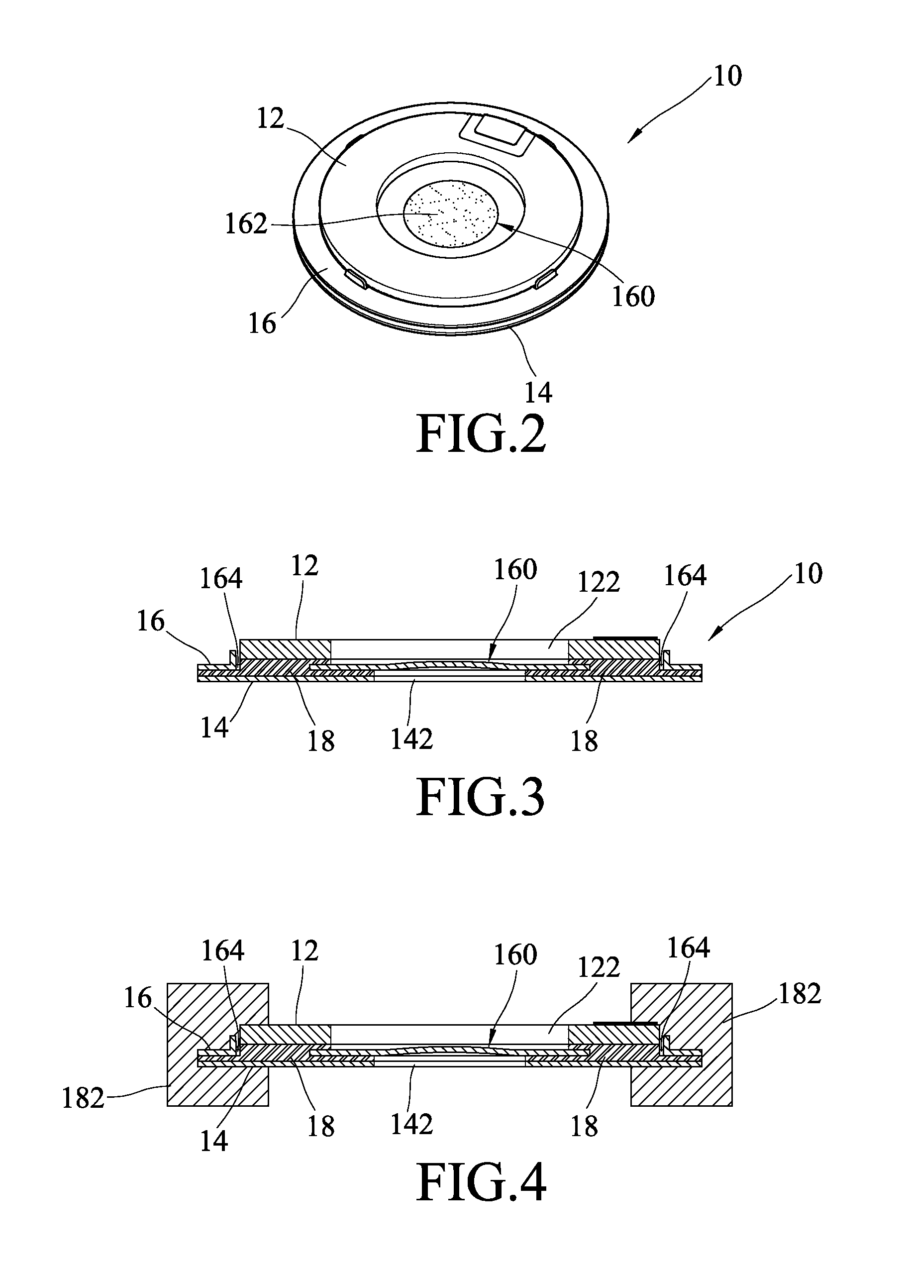
[0021]In the first embodiment, the microdroplet generation apparatus 10 is constructed via stacking together the abovementioned three plate-like structures, wherein the nozzle disc 16 is interposed between the oscillation plate 12 and the connection plate 14, and wherein the bonding material 18 joins the three plate-like structures together. As the nozzle disc 16 has the via-holes 164, the bonding material 18 can pass through the via-holes 164 to join the oscillation plate 12 and the connection plate 14 and fasten the nozzle disc 16 to between the oscillation plate 12 and the connection plate 14. Such a bonding method not only can effectively enhance the bonding strength of the oscillation plate 12 and the nozzle disc 16 but also can effectively transmit vibration energy from the oscillation plate 12 to the nozzle disc 16.

[0022]The bonding material 18 may be but not limited to a curable resin or a metallic soldering material.

[0023]Referring to FIG. 4, a sectional view schematically ...

second embodiment

[0028]In the second embodiment, the microdroplet generation apparatus 20 is constructed via stacking together the abovementioned four plate-like structures—the oscillation plate 22, the connection plate 24, the fixing plate 262 interposed between the oscillation plate 22 and the connection plate 24, and the nozzle disc 264 interposed between fixing plate 262 and the connection plate 24, wherein the bonding material 28 joins the four plate-like structures together. As the fixing plate 262 has the via-holes 2624, the bonding material 28 can pass through the via-holes 2624 to join the oscillation plate 22 and the connection plate 24 and fasten the fixing plate 262 and the nozzle disc 264 to between the oscillation plate 22 and the connection plate 24. Such a bonding method not only can effectively enhance the bonding strength of the oscillation plate 22 and the nozzle disc 262 but also can effectively transmit vibration energy from the oscillation plate 22 to the nozzle disc 262.

[0029]...


PUM


Abstract

A microdroplet generation apparatus comprises an oscillation plate, a connection plate, a nozzle disc and a bonding material, wherein the nozzle disc is interposed between the oscillation plate and connection plate, and wherein the oscillation plate, connection plate and nozzle disc are joined with the bonding material. The oscillation plate and the connection plate respectively have a first through-hole and a second through-hole corresponding to each other. The nozzle disc has injection holes on the area corresponding to the first and second through-holes. The nozzle disc has via-holes on the area not corresponding to the first through-hole and the second through-hole. The bonding material passes through the via-holes of the nozzle disc to join the oscillation plate and the connection plate and fasten the nozzle disc to between the oscillation plate and the connection plate. Thus, vibration energy can be effectively transmitted from the vibration plate to the nozzle disc.

Description

BACKGROUND OF THE INVENTION[0001]1. Field of the Invention[0002]The present invention relates to a microdroplet generation apparatus applying to a sprayer, particularly to a microdroplet generation apparatus having higher atomization efficiency.[0003]2. Description of the Related Art[0004]In the conventional sprayers and related prior arts, there are basically two means to generate atomized droplets. One is using the vibration of a piezoelectric material to squeeze a liquid out of a nozzle disc to generate microdroplets. Another means is using a piezoelectric material to vibrate a nozzle disc, and using the vibration of the nozzle disc to atomize a liquid into microdroplets. In some cases, the latter means adopts a liquid-vibration plane. For example, a bundle of capillary tubes is used to transport a liquid, and the terminals of the capillary tubes are fabricated into a plane. The liquid flowing to the plane is vibrated and atomized into microdroplets. Alternatively, a compressor i...

Claims


Application Information

Patent Timeline
IPC IPC(8): B05B1/08
CPCB05B17/0646
Inventor YU, SHAN-YILIU, HAN-CHANGTSAI, WEN-YU
Owner HEALTH & LIFE CO LTD
Why Eureka
Try Eureka