
Engine cylinder head intake port configuration

Active Publication Date: 2015-11-12
CHAMPION POWER EQUIP
View PDF2 Cites 7 Cited by
  • Summary
  • Abstract
  • Description
  • Claims
  • Application Information

AI Technical Summary

Benefits of technology

The invention relates to a cylinder head geometry for an internal combustion engine that reduces fuel puddling and improves fuel atomization. In one aspect, the cylinder head has an intake port with a modified D-shaped cross-section. In another aspect, the engine is configured to operate in both a horizontal and vertical crankshaft configuration. The intake port has first and second flat surfaces, and the cross-section of the intake port includes an arch surface and a chamfer surface. The engine includes a cylinder with an intake port and an exhaust port, which have different surfaces and a longitudinal surface. The technical effects of the invention are improved fuel atomization, reduced fuel puddling, and improved engine performance.

Problems solved by technology

Puddling of fuel in an intake passage of an internal combustion engine leads to several undesirable conditions.
In these conditions, the air stream within the intake manifold lacks sufficient velocity and turbulences to keep fuel in suspension.
When air stream velocity in the intake manifold increases due to acceleration, the fuel puddles are drawn into the combustion chamber and results in excess fuel present during combustion, which leads to incomplete combustion resulting in a surge of black smoke in the exhaust or backfiring through the carburetor.
When fuel puddles in the intake after shut down, upon start up, the result is an overly rich air / fuel mixture that can result in misfires and audible pops.
Accordingly, liquid fuel may not properly drain into the turbulent region when the engine operates in a second orientation.

Method used


Image

  • Engine cylinder head intake port configuration
  • Engine cylinder head intake port configuration
  • Engine cylinder head intake port configuration

Examples


Embodiment Construction

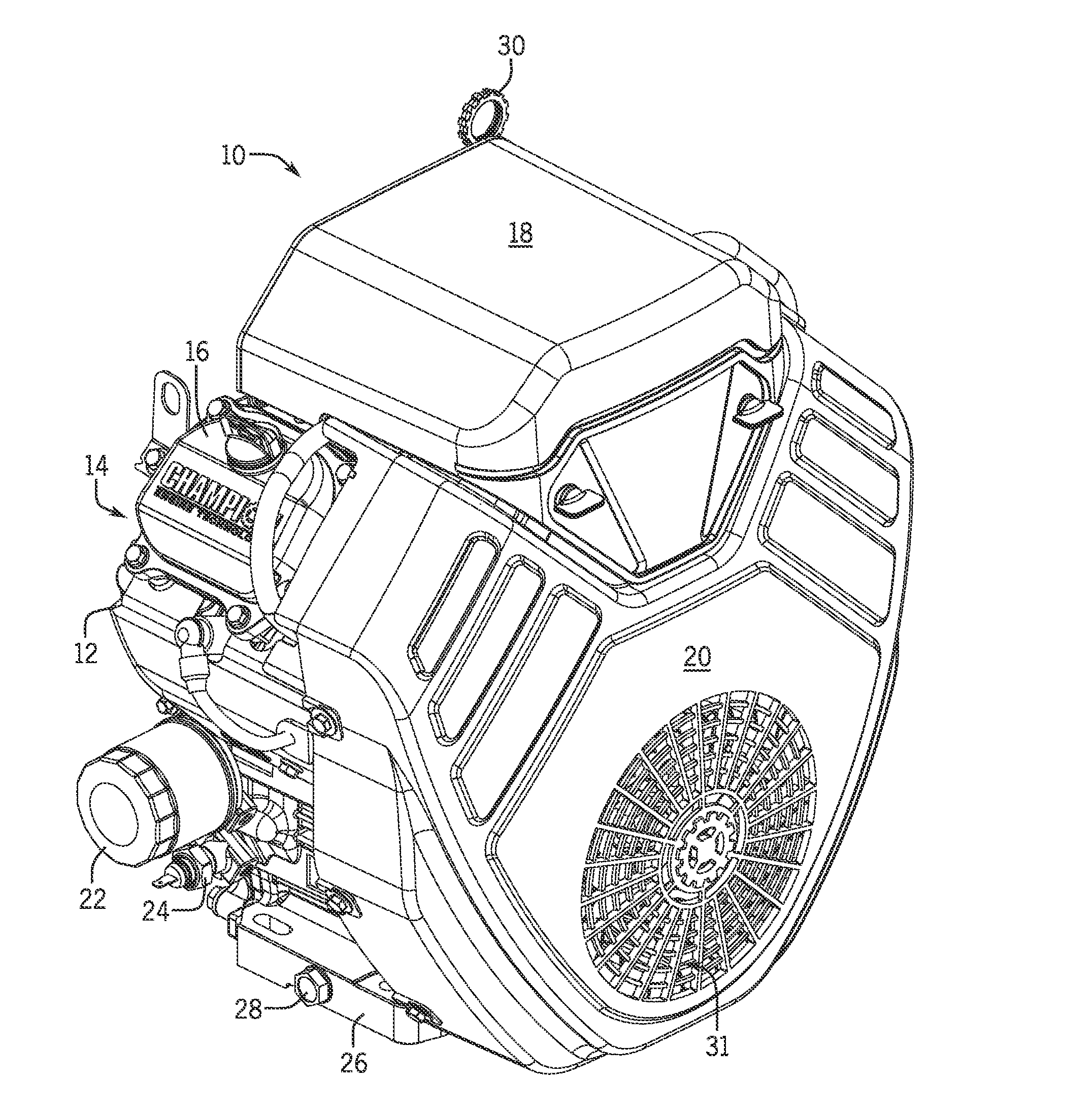
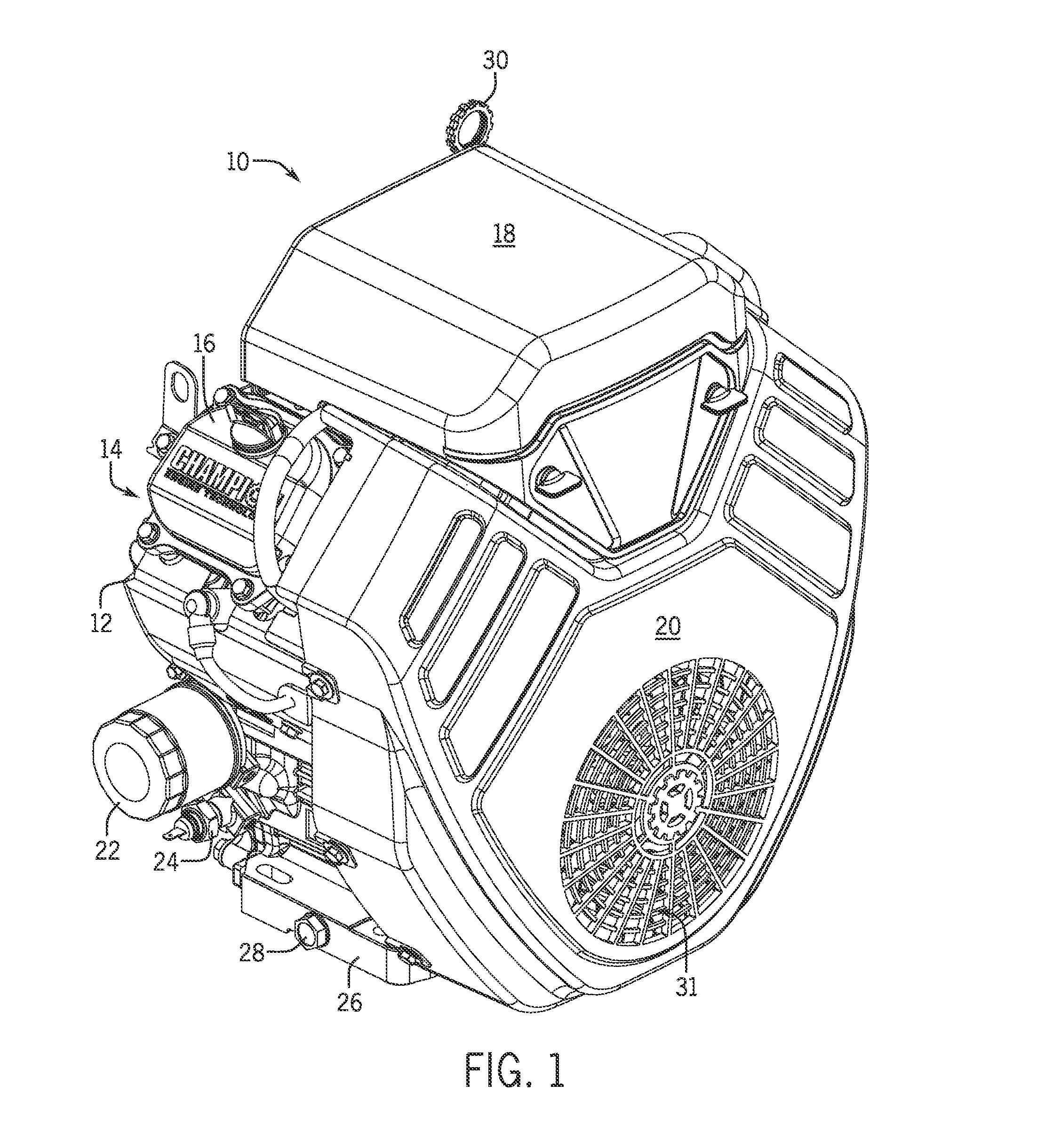
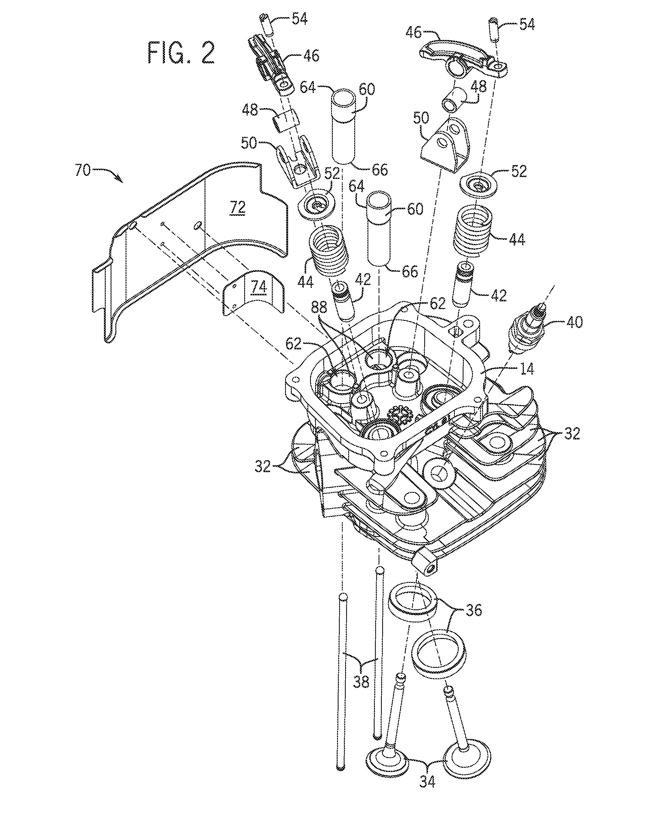
[0031]Embodiments of the invention are directed to an intake port of a cylinder head of an air cooled internal combustion engine; a push rod tube configuration within the cylinder head of the air cooled combustion engine; and an air guide for directing cooling air to the cylinder head of the air cooled combustion engine. The various embodiments of the invention are incorporated into the air cooled internal combustion engine, which in turn is incorporated as a prime mover / prime power source in any of a number of various applications, including but not limited to, power generators, lawnmowers, power washers, recreational vehicles, and boats, as just some examples. While embodiments of the invention are described below, it is to be understood that such disclosure is not meant to be limiting but set forth examples of implementation of the inventions. The scope of the inventions is meant to encompass various embodiments and any suitable application in which a general purpose internal com...


PUM


Abstract

A cylinder head for an internal combustion engine is disclosed having an intake port geometry configured to reduce fuel puddling and improve fuel atomization. The cylinder head includes a housing having a recess defining a top portion of a combustion chamber. The cylinder head further includes intake and exhaust ports defined by channels extending from the top portion of the combustion chamber to an outer end of the housing. An intake valve is positioned within the cylinder head to control communication of the intake port with the combustion chamber, and an exhaust valve is positioned within the cylinder head to control communication of the exhaust port with the combustion chamber. The intake port further includes a cross-section having a modified D-shape with a single 90 degree corner. The modified D-shape cross-section extends substantially a length of the intake port.

Description

BACKGROUND OF THE INVENTION[0001]Embodiments of the invention relate generally to cylinder head intake port configuration for internal combustion engines and, more particularly, to intake port geometry configured to reduce fuel puddling and improve fuel atomization.[0002]Puddling of fuel in an intake passage of an internal combustion engine leads to several undesirable conditions. Fuel puddling occurs when an engine is shut down or is run at very low speeds. In these conditions, the air stream within the intake manifold lacks sufficient velocity and turbulences to keep fuel in suspension. As a result, liquid fuel tends to settle out and collect in low areas of the intake.[0003]When running at low speeds, liquid fuel present in the intake port may drain into the combustion chamber through the intake valve. When air stream velocity in the intake manifold increases due to acceleration, the fuel puddles are drawn into the combustion chamber and results in excess fuel present during comb...

Claims


Application Information

Patent Timeline
IPC IPC(8): F02F1/24
CPCF02F1/24F02F1/42F02M35/10F02M35/10124F02F1/4235F02B63/02F02B63/048F02M35/10262F02M35/10281F02M35/10288F02M35/1017Y02T10/12
Inventor DOPKE, RUSSELL J.DEHN, JAMES J.
Owner CHAMPION POWER EQUIP
Learn More