Container assembly for a substance to be applied

Inactive Publication Date: 2006-01-03
IVOCLAR VIVADENT AG
View PDF23 Cites 41 Cited by
  • Summary
  • Abstract
  • Description
  • Claims
  • Application Information

AI Technical Summary

Benefits of technology

[0019]In this embodiment, it is provided that a closure cap can be deployed on the injector housing. Such closure caps are in any event commercially available for the clip lock system. Preferably, in accordance with the present invention, the closure cap can itself be provided with a corresponding marking in order to reliably preclude the risk that contamination can occur by the placement in error of the closure cap on the non-associated one of a pair of inje

Problems solved by technology

This approach is, however, clearly more expensive and requires a higher production precision for conforming the layer thicknesses to one another, for securing the layers to one another, and for assuring the sealing integrity.
A disadvantage of the heretofore deployed systems lies in the fact that the injector components must be manufactured together with the application tip.
However, there exists the problem th

Method used


Image

  • Container assembly for a substance to be applied
  • Container assembly for a substance to be applied
  • Container assembly for a substance to be applied

Examples


Example

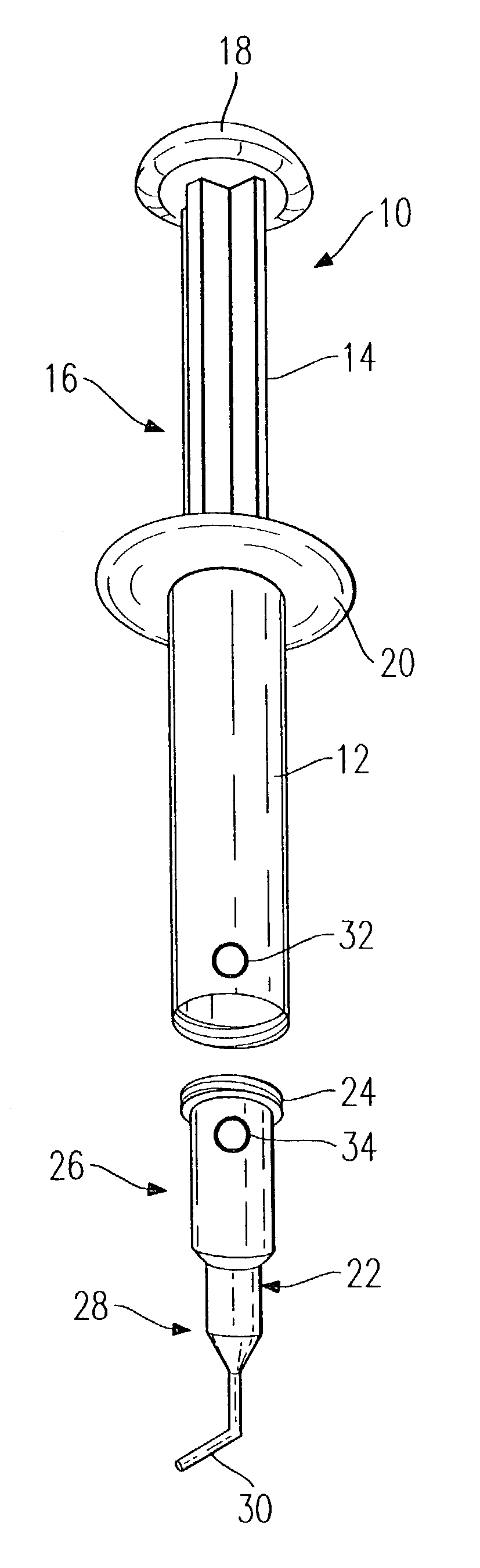
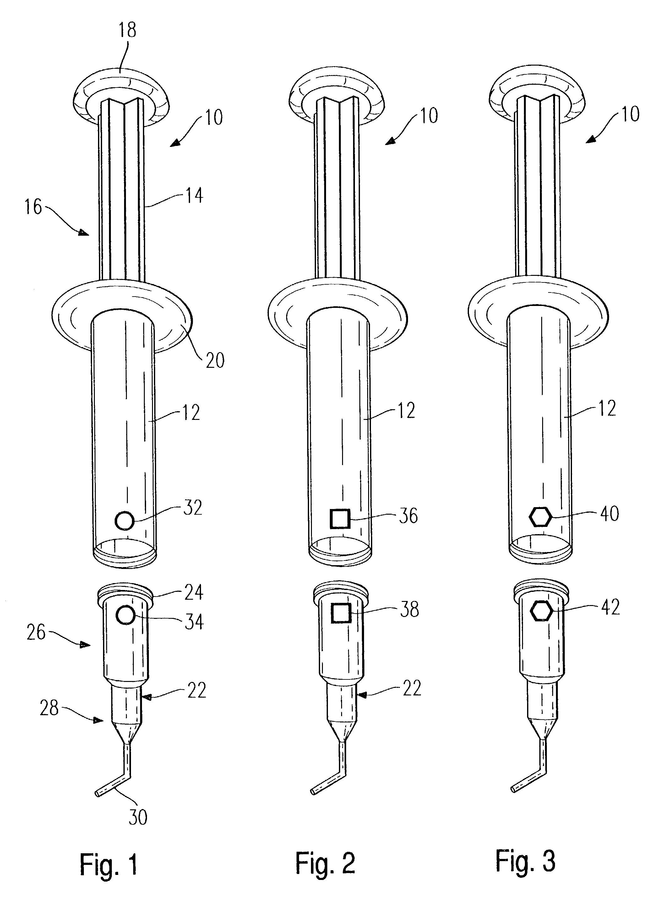
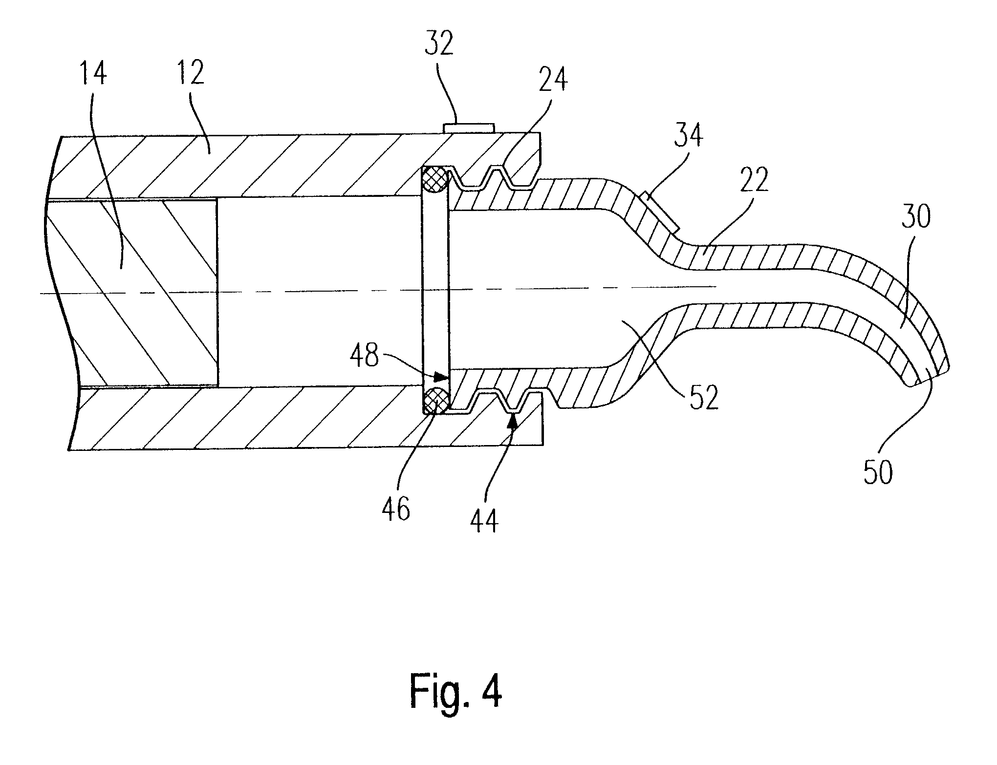
[0030]As shown in FIG. 1, an injector 10 includes an injector housing 12 which guides therein an injector plunger 14. With respect to the injector plunger 14 shown in FIGS. 1–3, only the shaft thereof is visible. To produce the required pressure, the shaft 16 includes a knob 18 on its outward end. In this connection, the injector housing 12 comprises a grip flange 20. A substantially large injection pressure can be applied by pressing together the knob 18 and the grip flange 20 between the palm of the hand and, for example, the middle and index finger, whereby the thus-applied pressure effects the forward movement or injection of the pasty mass contained in the injector housing 12.

[0031]An application tip 22 is connected to the forward portion of the injector housing 12. In this connection, the injector housing 12 comprises a substantially curved inner thread course at its forward end having a correspondingly large pitch. An outer thread course 24 on the rearward end of the applicat...


PUM


Abstract

A container assembly for a substance to be applied is provided that includes a injector housing, an application tip, and a closure cap. The application tip and the closure cap are alternatively removably securable to the outlet end of the injector housing in a substantially fluid tight disposition. A first indicia is associated with the injector housing and a second indicia is associated with each of the application tip and the closure cap. The second indicia has an identity correspondence with the first indicia such that the presence of both the first indicia on the injector housing and the second indicia on the respective one of the application tip and the closure cap secured to the outlet end of the injector housing confirms that only the appropriate application tip or the appropriate closure cap has been secured to the injector housing.

Description

CROSS-REFERENCE TO RELATED APPLICATIONS[0001]This application claims foreign priority benefits under 35 U.S.C. §119(a)–(d) from German patent application ser. no. P 101 51 404.2 filed Oct. 18, 2001. In addition, this application claims the benefit under 35 U.S.C. §119(e) of U.S. provisional patent application Ser. No. 60 / 334,303 filed Nov. 29, 2001.TECHNICAL FIELD[0002]The present invention relates to a container for a substance to be applied.BACKGROUND OF THE INVENTION[0003]Containers of this type, which can be configured as, for example, injectors, have long been known. In EP-A1-0 063 891, one approach to configuring such a container includes an application tip with a closure cap, whereby pasty material is provided in the application tip. A plunger ram pushes an injection plunger into an injector housing, whereby the corresponding geometrical configuration of the injector plunger is chosen such that only the smallest possible remaining amount of material remains in the injector ho...

Claims


Application Information

Patent Timeline
IPC IPC(8): A61C5/04A61C5/06A61M5/34
CPCA61C5/062B05C17/00593A61C2202/01A61M5/347A61M2205/6081B05C17/00506B05C17/00516A61M2205/6045A61C5/62
Inventor REISINGER, MICHAEL
Owner IVOCLAR VIVADENT AG
Why Eureka
Try Eureka