Image processing method, image processing apparatus, and conveyor line system using image processing apparatus

a technology of image processing and image processing equipment, which is applied in the direction of inking apparatus, duplicating/marking methods, printing, etc., can solve the problems of thermoreversible recording medium coloring density decline, etc., to improve machine-readability and improve throughput per day without deterioration

Inactive Publication Date: 2016-09-22
RICOH KK
View PDF4 Cites 1 Cited by
  • Summary
  • Abstract
  • Description
  • Claims
  • Application Information

AI Technical Summary

Benefits of technology

[0011]According to the present invention, there can be provided an image processing method which can prevent an image to be recorded from decreasing in coloring density without deteriorating throughput per day and can improve machine-readability of, for example, a barcode even when at least one of a surface temperature of a thermoreversible recording medium and a recording environmental temperature is suddenly increased to an unexpected level.

Problems solved by technology

The thermoreversible recording medium having such property as described above is problematic in that, under a high temperature environment, the thermoreversible recording medium is decreased in coloring density since the thermoreversible recording medium which has been heated is difficult to be rapidly cooled.
On the other hand, under a low temperature environment, there also is a problem that the thermoreversible recording medium is decreased in the coloring density since the thermoreversible recording medium is difficult to be held within the decoloring temperature range after the thermoreversible recording medium is heated.

Method used


Image

  • Image processing method, image processing apparatus, and conveyor line system using image processing apparatus
  • Image processing method, image processing apparatus, and conveyor line system using image processing apparatus
  • Image processing method, image processing apparatus, and conveyor line system using image processing apparatus

Examples


example 1

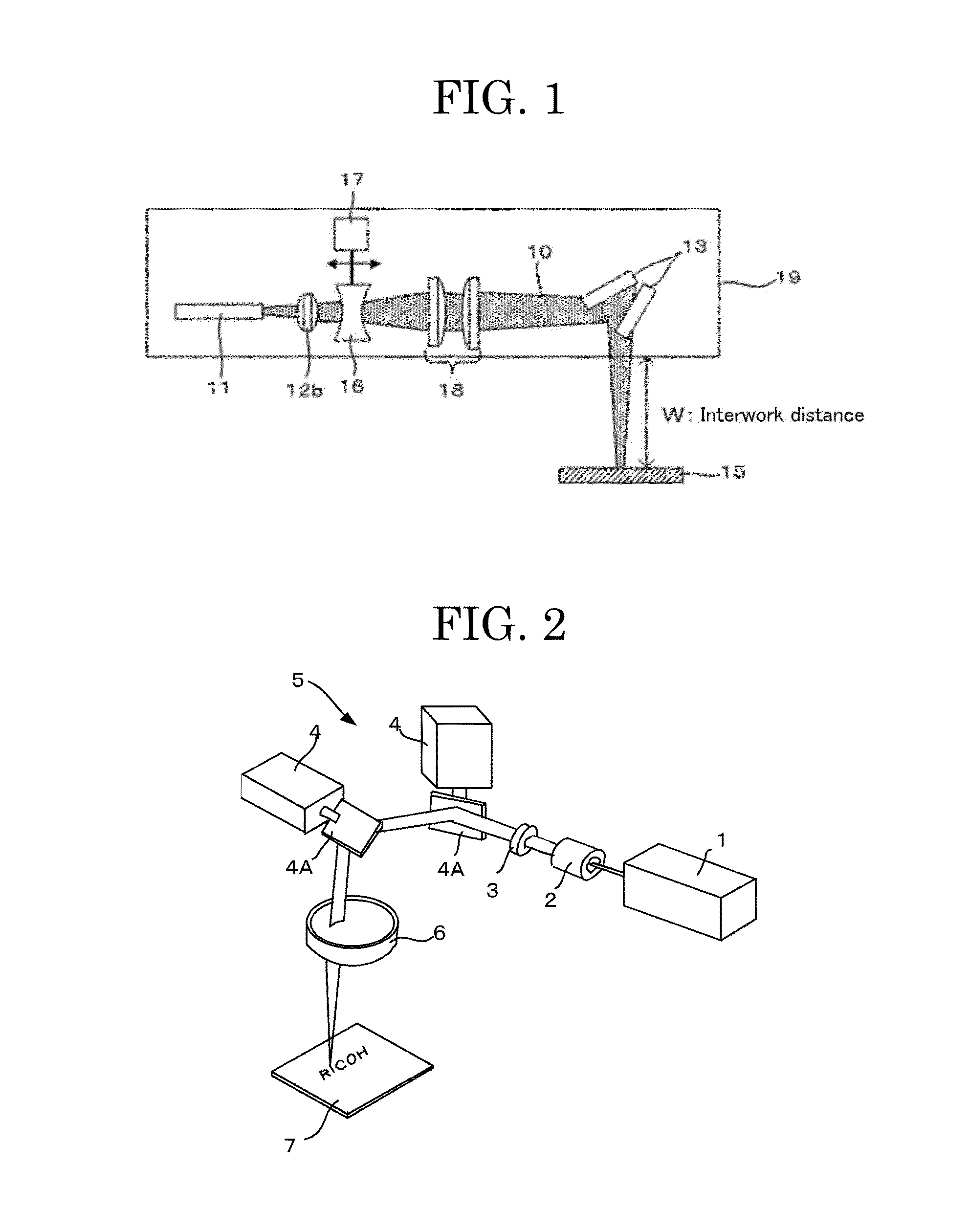
[0167]As illustrated in FIG. 1, an optical system was formed in which laser beams are emitted from a fiber-coupled laser diode beam source ELEMENT™ E12 (manufactured by nLIGHT Corporation, central wavelength: 976 nm, maximum emitting power: 105 W) serving as the laser beam source 11, collimated by a collimator lens 12b disposed in the downstream of an optical path of the emitted laser beams, and then concentrated by the focal length control unit 16 and the condenser lens 18 disposed in the downstream of the collimator lens. Thereafter, a galvanoscanner 6230H (manufactured by Cambridge Inc.) disposed in the downstream side of the optical system scanned the laser beams to irradiate the thermoreversible recording medium with the laser beams, to thereby rewrite an image.

[0168]The thermoreversible recording medium was fixed so that the interwork distance from an optical head surface of the fiber-coupled laser diode beam source to the thermoreversible recording medium was 150 mm, and a sp...

example 2

[0197]The barcode image, density of the solid image, and the line image were evaluated and the average processing time per container for a daily operating time was determined in the same manner as in Example 1, except that the surface temperature sensor was set to ON and the environmental temperature sensor was set to OFF in order to set the surface of the thermoreversible recording medium as the target to be measured. Results are presented in Tables 1-1 and 1-2.

example 3

[0198]The barcode image, density of the solid image, and the line image were evaluated and the average processing time per container for a daily operating time was determined in the same manner as in Example 1, except that the time interval at the recording environmental temperature of 35° C. or higher was changed to 0.5 seconds and the pulse width upon image recording was decreased by 2% for correcting the time interval to thereby decrease the irradiating energy of laser beams. Results are presented in Tables 1-1 and 1-2.


PUM

PropertyMeasurementUnit
wavelengthaaaaaaaaaa
emitting poweraaaaaaaaaa

Abstract

Provided is an image processing method, the method including heating a thermoreversible recording medium with laser beams to erase an image which has been recorded on the thermoreversible recording medium, the thermoreversible recording medium reversibly changing between a colored state and a decolored state depending on a heating temperature and a cooling time; heating the thermoreversible recording medium, on which the image has been erased, with the laser beams to record a subsequent image on the thermoreversible recording medium; and measuring at least one of a surface temperature of the thermoreversible recording medium and a recording environmental temperature after a completion of erasing the image but before a beginning of recording the subsequent image to obtain a measured temperature value and controlling a time interval between the completion of erasing the image and the beginning of recording the subsequent image depending on the measured temperature value.

Description

CROSS-REFERENCE TO RELATED APPLICATIONS[0001]The present application claims priority under 35 U.S.C. §119 to Japanese Patent Application No. 2015-057032, filed Mar. 20, 2015. The contents of which are incorporated herein by reference in their entirety.BACKGROUND OF THE INVENTION[0002]1. Field of the Invention[0003]The present invention relates to image processing methods, image processing apparatuses, and conveyor line systems using the image processing apparatuses.[0004]2. Description of the Related Art[0005]Recently, an image processing apparatus using a thermoreversible recording medium has been incorporated into and utilized in a conveyor line system which needs to manage a conveying container (e.g., returnable container employed in a physical distribution system). The thermoreversible recording medium is attached on the conveying container as a label and is rewritable with laser beams emitted from the image processing apparatus in a non-contact manner. This eliminates a need fo...

Claims


Application Information

Patent Timeline
Patent Type & Authority Applications(United States)
IPC IPC(8): B41M7/00
CPCB41M7/0009B41J2/32B41J2/47B41J2202/37B41M5/305B41J2/4753
Inventor ISHIMI, TOMOMIKAWAHARA, SHINYAASAI, TOSHIAKIOHI, KATSUYA
Owner RICOH KK
Why Eureka
Try Eureka