Centrifugal casting method for forming a frame and defining mould therefor

a centrifugal casting and frame technology, applied in the direction of lamination, fuel cells, applications, etc., can solve the problems of obstruction of membranes, inability to use injection moulding methods, and destruction of filter means

Inactive Publication Date: 2009-08-20
IP HLDG LLC
View PDF9 Cites 0 Cited by
  • Summary
  • Abstract
  • Description
  • Claims
  • Application Information

AI Technical Summary

Benefits of technology

[0004]The object of the present invention is therefore to provide a method with which a form-fitting edge enclosure can be formed around at least one flat disc-shaped element. In particular, at least two disc-shaped elements are to be connectable to one another to form a disc-shaped element, which connection is to be effected in a material-preserving and durable manner. Furthermore, the joining of a wide variety of materials is to be possible with the method and at the same time the individual elements are to be joined in a sealing manner.

Problems solved by technology

The mechanical stress of the welding in the edge region thus leads to the production of kinks in the fine membrane material, which subsequently, in particular during backwashing steps, may lead to the destruction of the filter means.
Injection moulding methods are not usable, for example, in the case of fine-pored membrane filters, metal or polymer membranes, since the capillary action here leads to the penetration of the plastic material or joining material into the membrane and thereby the obstruction of the membranes, so that a considerable part of the filter area is lost or the filter fabric is completely obstructed.
Such problems arise in the case of the edge connection of a plurality of layers of a porous or net-like fabric to form a sandwich-like disc-shaped element of another kind, not only in the production of filter means.
Huge leak-tightness problems are constantly arising in this regard.

Method used


Image

  • Centrifugal casting method for forming a frame and defining mould therefor
  • Centrifugal casting method for forming a frame and defining mould therefor
  • Centrifugal casting method for forming a frame and defining mould therefor

Examples


Embodiment Construction

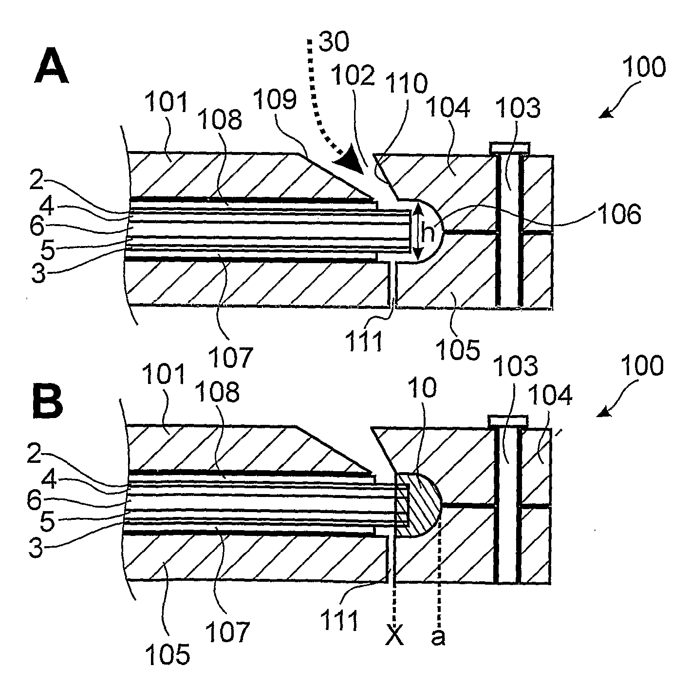
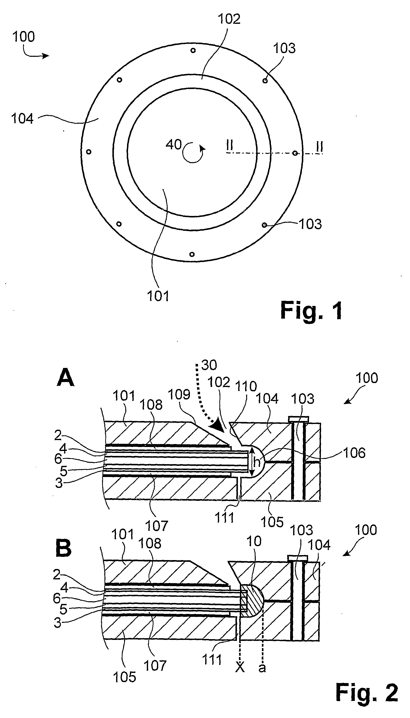
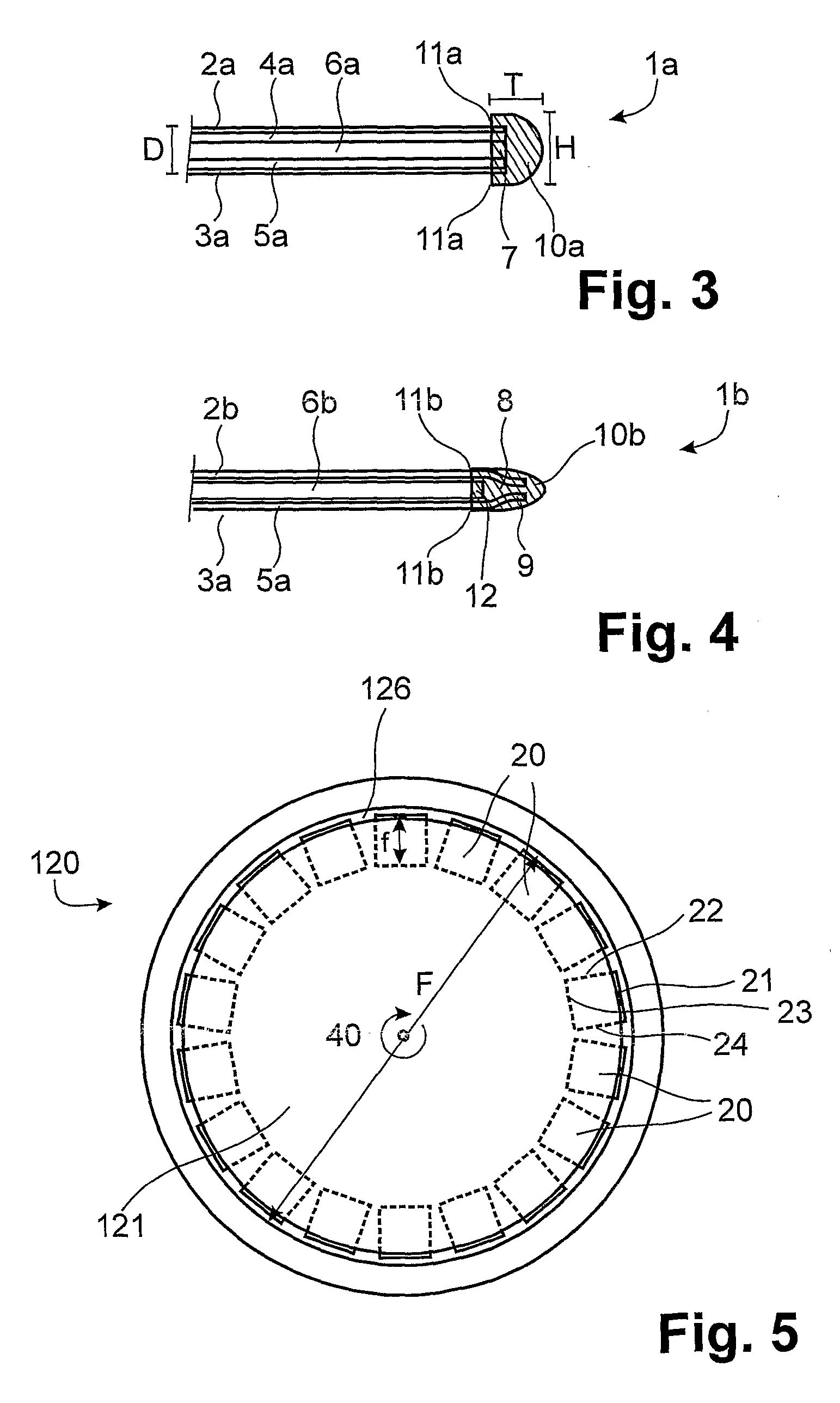
[0041]The method according to a preferred embodiment of the invention, and also the structure of a defining mould according to the invention, become clear when FIGS. 1-4 are viewed together. By way of example, the production of a disc-shaped element in the form of a filter means 1 is presented.

[0042]The defining mould 100 comprises an upper part 104 and a lower part 105. These parts are connected to one another via bolts 103 to form the defining mould 100. Also provided is a cover 101, which is placed in a centred manner upon the laid-in elements 2, 3, 4, 5 and 6. If necessary, the cover 101 may be fixed to the upper part 104 and / or the lower part 105. In principle, the cover 101 may also be dispensed with. It has proved advantageous, however, to provide a cover, since a certain contact pressure is thereby provided, by which the laid-in elements 2-6 are brought close together and are held together, so that they remain exactly on top of one another even during the rotating operation....


PUM

PropertyMeasurementUnit
angleaaaaaaaaaa
thicknessaaaaaaaaaa
diameteraaaaaaaaaa

Abstract

The invention relates to a method for forming an edge enclosure. A defining mould (100) is provided, in which at least one disc-shaped element (2, 3, 4, 5, 6) is arranged and which surrounds the element at least at the edge. The at least one element is set in rotation (40), whereby casting compound introduced into the defining mould localises in the edge region (7) of the at least one element and cures there, so as to produce an edge enclosure (10) which at least partially surrounds the at least one element in a form-fitting manner.

Description

FIELD OF INVENTION[0001]The present invention relates to a method with which at least one disc-shaped element, for example a filter means, can be bordered and enclosed in a form-fitting manner. Furthermore, it relates to a defining mould for use in the method.BACKGROUND[0002]In the art, it is often necessary to enclose a flat, disc-shaped element with a form-fitting border or to join together a plurality of flat, disc-shaped elements. One possibility for such a connection is the edge bond by means of an edge enclosure. This bond is essential in the case of certain disc-shaped elements, e.g. filter means. A filter means is an element which is used in a filtration device and which effects the actual filtration process, e.g. the separation of specific substances. Frequently, a plurality of filter means are used in a single filtration device. Filter means are usually of multilayer construction, a courser drainage fabric generally being arranged in the middle and surrounded by at least o...

Claims


Application Information

Patent Timeline
Patent Type & Authority Applications(United States)
IPC IPC(8): B29C41/30
CPCB29C39/08B29C39/10Y02E60/50H01M8/028H01M8/0286H01M8/0273
Inventor RUDOLF, ERHARDGLUECK, MARKUSFASTNER, FRANZ
Owner IP HLDG LLC
Why Eureka
Try Eureka