Terminus cap for a drive cable, drive cable, method for the production of a terminus cap, and method for the production of drive cable

a technology for terminating caps and drives, which is applied in the direction of couplings, shafts for linear movement, and cables for vehicles/pulleys. it can solve the problems of reducing the tendency of drive cables to rattle, and achieve cost-effective production, easy and reliable attachment, and cost-effective

Inactive Publication Date: 2010-12-09
MEFLEX TELECONTROL GMBH & CO KG
View PDF11 Cites 1 Cited by
  • Summary
  • Abstract
  • Description
  • Claims
  • Application Information

AI Technical Summary

Benefits of technology

[0029]Another aspect of the invention relates to a method for the production of an end cap in accordance with the invention described above. The method according to the invention provides for the preparation of a connecting section and for the attachment of an end section to the connecting section. An end cap produced according to this method is very sturdy, can be easily and reliably attached to the end of the drive cable, does not tend to rattle and can also be produced cost-effectively.
[0030]Particularly advantageously, the end section can be attached to the connecting section by means of insertion, ultrasound welding, thermal upsetting, plastic cold-forming, driving in or by means of direct injection molding. These methods allow a particularly cost-effective production of the end caps while attaining a high level of quality.
[0031]Moreover, it can be advantageously provided that the end section and the connecting section are manufactured separately and then clipped together. This translates into a particularly easy assembly.
[0032]Furthermore, it can be provided that the end section ...

Problems solved by technology

However, the end section made of plastic also reduces the tendency of t...

Method used


Image

  • Terminus cap for a drive cable, drive cable, method for the production of a terminus cap, and method for the production of drive cable
  • Terminus cap for a drive cable, drive cable, method for the production of a terminus cap, and method for the production of drive cable
  • Terminus cap for a drive cable, drive cable, method for the production of a terminus cap, and method for the production of drive cable

Examples


first embodiment

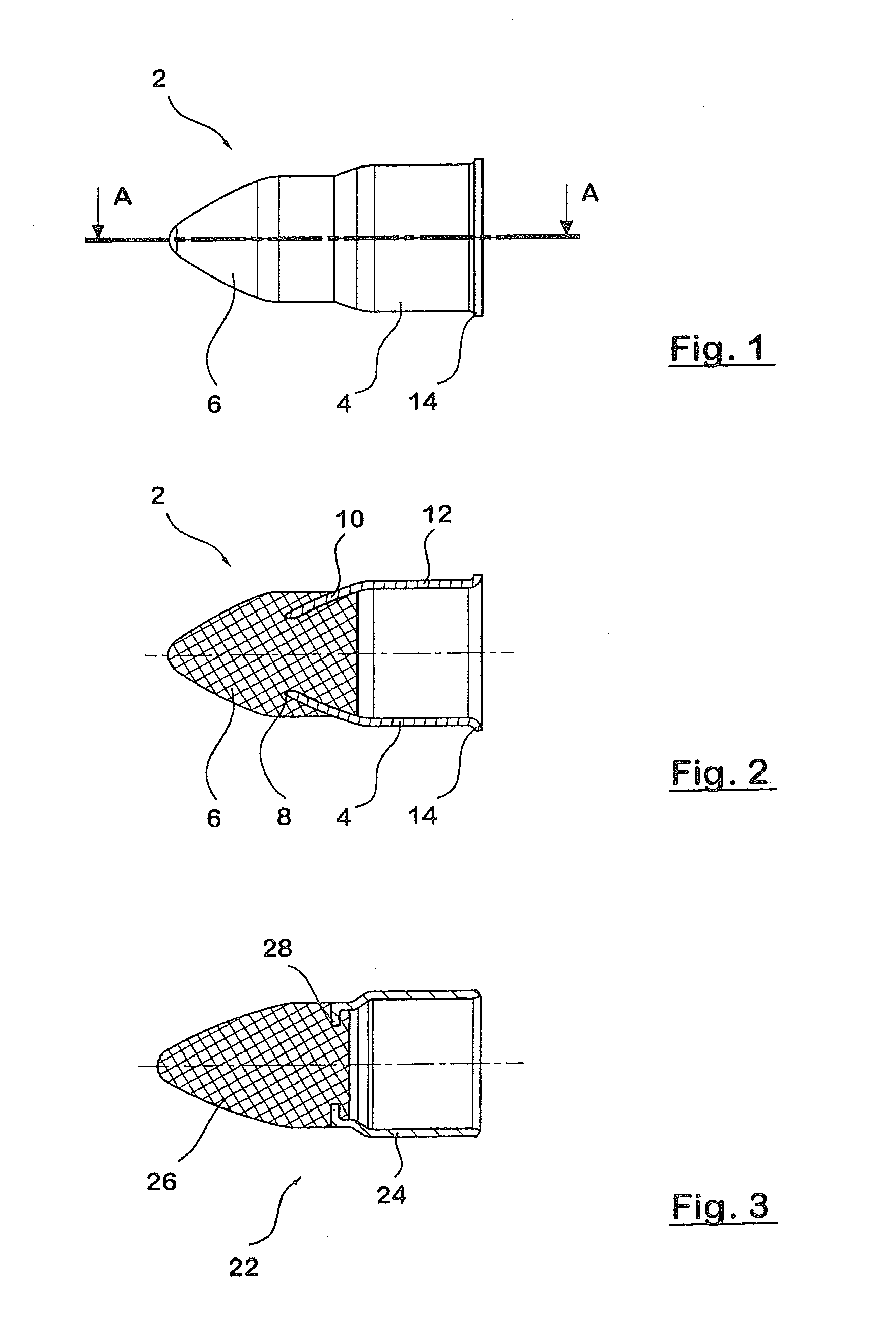
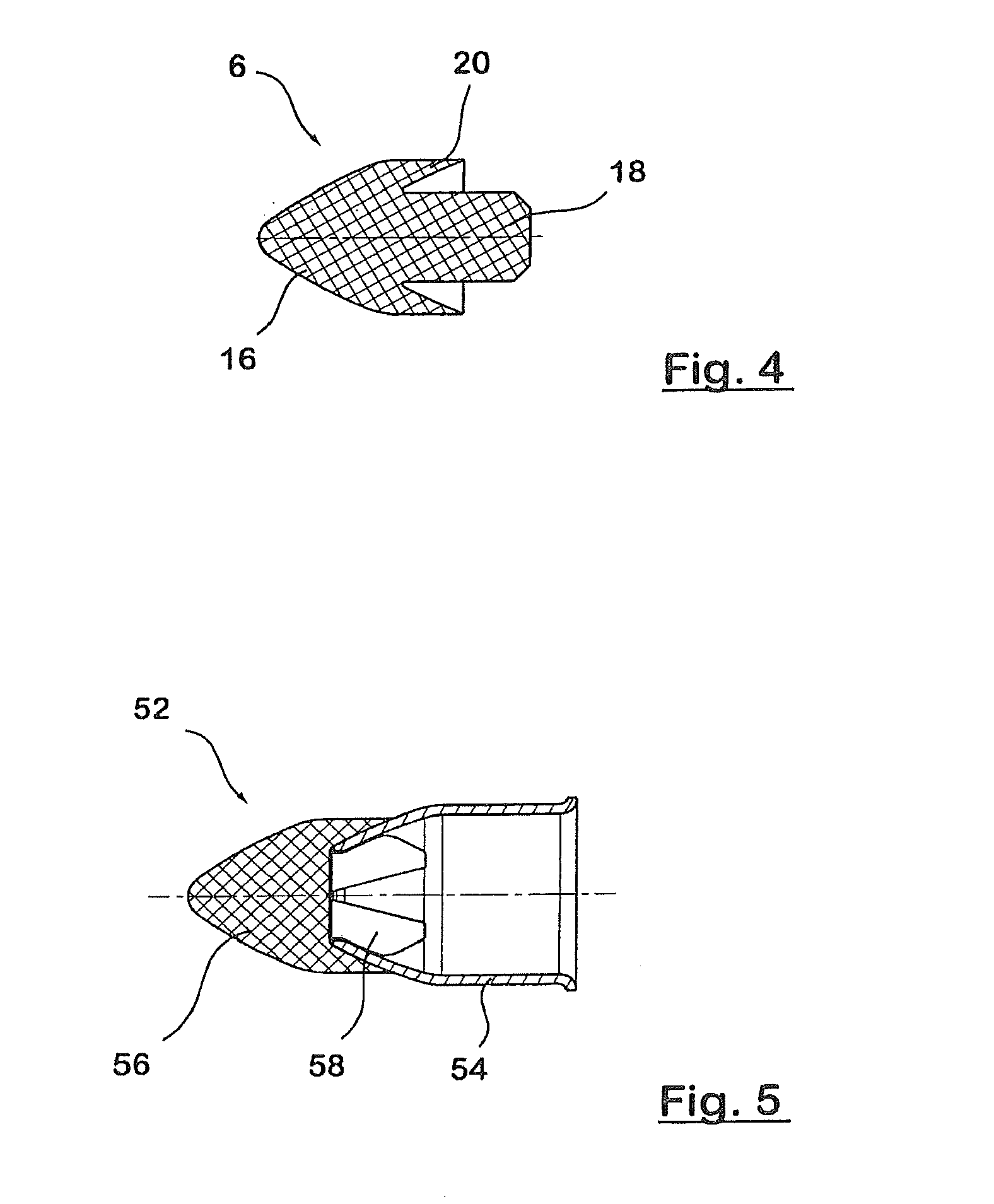
[0057]FIG. 5 shows another alternative of an end cap 52 according to the invention. In contrast to the first embodiment shown in FIGS. 1 and 2, a front end section 56 that is injection-molded onto a connecting section 54 is positively fastened by means of a slotted and shaped rear area 58. In this embodiment, the end section 56 can be joined to the connecting section 54 by clipping them together.

[0058]FIGS. 6a to 6c show a drive cable 32 known from the state of the art. FIG. 6a depicts a side view of the drive cable 32. The drive cable 32 is closed on its front end by a sleeve 34 in order to prevent the drive cable 36 from splaying. The prior-art sleeve 34 is made of metal and is fastened to the end of the drive cable 36 by means of hammering.

[0059]FIG. 6b shows a cross section through the cable from FIG. 6a. The end of the drive cable 32 protrudes into the end cap 34 all the way to the conically tapered area of the end cap 34.

[0060]FIG. 6c shows a cross section of the end cap 34 kn...

fourth embodiment

[0062]FIG. 8A shows an end section 66 of an end cap according to a The end section 66 has a front section 66.1 as well as a rear section 66.2 that is inserted into a connecting section 64 shown in FIG. 8B into an opening 68 provided for this purpose.

[0063]The opening 68 of the connecting section 64 has a diameter Z that is smaller than the largest diameter X of the end section 66.2. During the insertion, it can be achieved here that the end section 66 fits securely in the opening 68 of the connecting section 64 provided for this purpose, so that it cannot fall out. In the fourth embodiment, the assembly can be carried out by a simple insertion. The secure fit can be additionally improved by hammering the connecting section 64 after the end section 66 has been inserted, as a result of which the diameter Z of the opening 68 of the connecting section 64 is further reduced in the manner described above, thus achieving an additional clamping effect.

[0064]Of course, the appertaining comp...


PUM

PropertyMeasurementUnit
Diameteraaaaaaaaaa
Areaaaaaaaaaaa
Thermoplasticityaaaaaaaaaa

Abstract

A terminus cap (2; 22; 52; 62) for a drive cable has a connection section (4; 24; 54; 64), which can be cold-formed, on the drive cable, and an end section (6; 26; 56; 66) made of plastic. The connection section (4; 24; 54; 66) has an opening (8; 28; 68) pointing toward the end section (6; 26; 56; 66), and the end section (6; 26; 56; 66) engages partially in the opening (8; 28; 68). An end section (6; 26; 56; 66) of the terminus cap (2; 22; 52; 62) may be fastened on the connection section (4; 24; 54; 64) of the drive cable. The drive cable with terminus cap can be used in pop-up and/or sliding roofs or sunscreen roller blinds of motor vehicles.

Description

CROSS-REFERENCE TO RELATED APPLICATIONS[0001]This application is a national stage application (under 35 U.S.C. §371) of PCT / EP2009 / 000445, filed Jan. 23, 2009, which claims benefit of German applications 10 2008 005 983.8, filed Jan. 24, 2008 and 10 2008 022 313.1, filed May 6, 2008.TECHNICAL FIELD[0002]The invention relates to an end cap for a drive cable that is used especially in motor vehicles, for example, in sliding and / or tilting sunroofs, or in roller blinds such as, for instance, sun blinds. The invention also relates to a drive cable having such an end cap, as well as to a method for the production of an end cap and to a method for the production of a drive cable.BACKGROUND ART[0003]Drive cables or transmission cables of the above-mentioned type are disclosed, for example, in European patent applications EP 0 409 103 A2 and EP 0 181 995 A2. Such drive cables are preferably employed for sliding and / or tilting sunroofs of motor vehicles, whereby the drive cables can usually ...

Claims


Application Information

Patent Timeline
IPC IPC(8): F16C1/10B23P11/00
CPCF16G11/00Y10T29/49908Y10T403/4966F16G11/02
Inventor ABENDROTH, BERNDKUSTER, KLAUS
Owner MEFLEX TELECONTROL GMBH & CO KG
Why Eureka
Try Eureka