Method for producing prefabricated structural parts

a technology of structural components and prefabricated parts, which is applied in the direction of walls, building components, constructions, etc., can solve the problems of high cost and effort, inability to precisely produce the bottom plate, and difficulty in alignment of structural components on construction sites, so as to achieve easy and reliable attachment and easy attachment to other structural components

Inactive Publication Date: 2013-08-15
REDLBERGER ALFRED
View PDF8 Cites 1 Cited by
  • Summary
  • Abstract
  • Description
  • Claims
  • Application Information

AI Technical Summary

Benefits of technology

[0014]It is advantageous to provide the features of claim 6 in order to ensure that the bottom plates are easily and reliably attached to the other bottom plates.
[0015]The features of claim 7 provide the advantage of producing a vertical wall that can be easily attached to other structural components without further adjustment.

Problems solved by technology

Producing the bottom plate requires prior working procedures that are very costly.
In addition, a precise bottom plate can be produced only with great difficulty.
There is also a further problem if watertight building components are required as otherwise water can penetrate through the construction joint between the bottom plate and the wall plate.
Another disadvantage results from the fact that the alignment of the structural components at the construction site entails very significant cost and effort, and also a corresponding cost and effort to support the structural components in order to retain them in the desired position.
This requires several workers and a corresponding input in time, which means higher construction costs.

Method used


Image

  • Method for producing prefabricated structural parts
  • Method for producing prefabricated structural parts
  • Method for producing prefabricated structural parts

Examples


Embodiment Construction

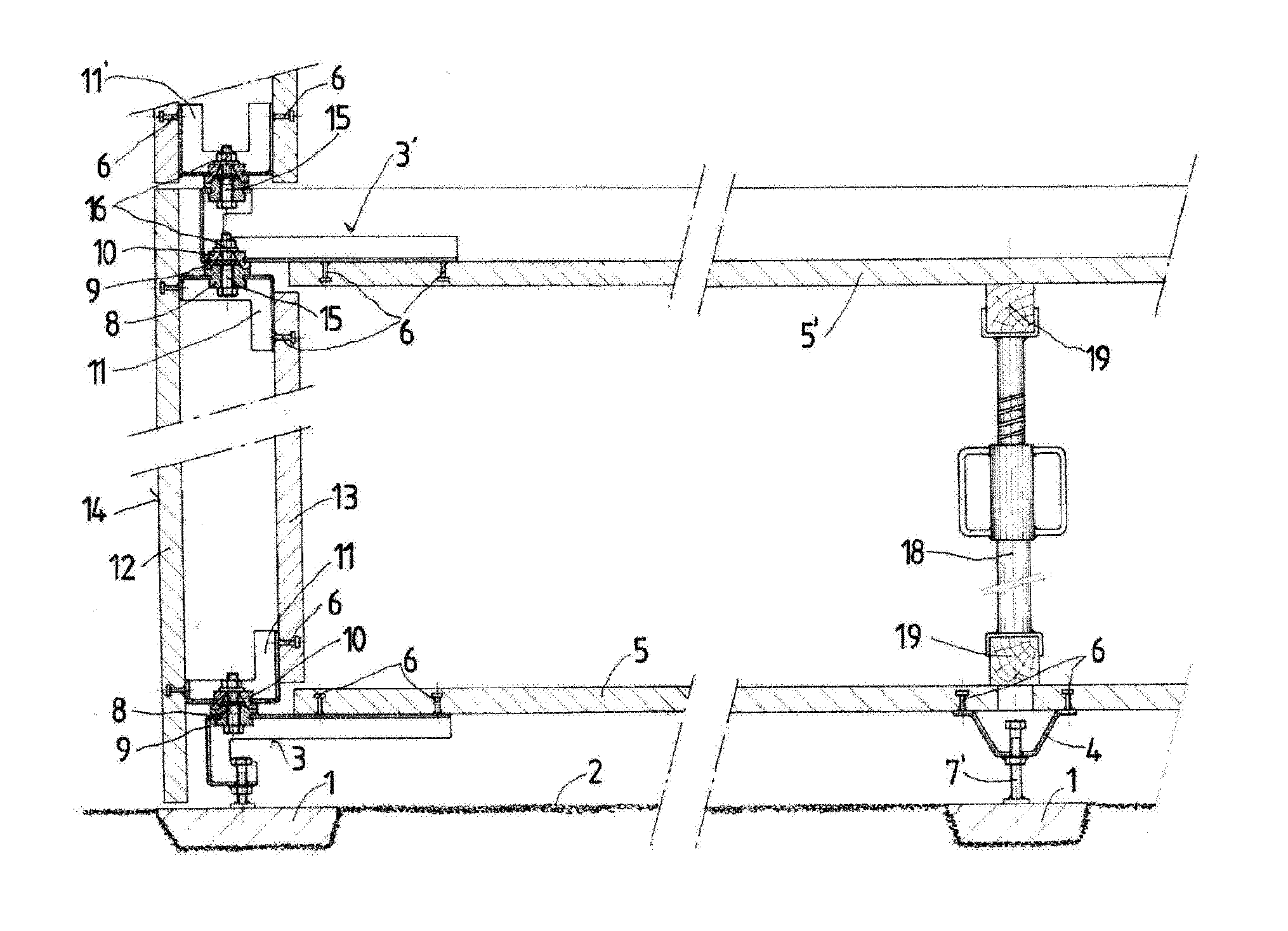
[0006]The object of this invention is to avoid these disadvantages and to propose a method of the type described above where prefabricated structural components can be produced that do not have a construction joint between the bottom plate and the wall plate, that enables a precise bottom plate to be produced where no essential prior work procedures are required to produce the bottom plate, and where simple installation of the produced structural components is made possible at the construction site, thereby significantly reducing the cost of erecting the prefabricated-component building and significantly enhancing the quality of construction.

[0007]This is achieved according to the invention in a method of the type mentioned above by the characterizing features of claim 1.

[0008]Shaping the parts is done after the mounting fittings have been installed in the plates or double-walled plates under controlled workshop conditions so as to ensure a corresponding precision for the parts. Aft...


PUM

PropertyMeasurementUnit
hardenableaaaaaaaaaa
dimensionsaaaaaaaaaa
heightaaaaaaaaaa

Abstract

The invention relates to a method for producing prefabricated structural parts (5, 14) from a setting plastic compound for erecting buildings, in which the setting compound is filled into a shuttering and left to set into panels, two panels (12, 13) being joined together if necessary by means of reinforcements placed into the shutterings to form a double-walled panel (14). The built-in parts (3, 4, 20, 20′), which serve for the adjustable support of the prefabricated structural parts and/or for joining them to one another, are attached to the edge regions of the panels or double-walled panels, wherein the built-in parts (3, 11, 11′, 20, 20′) have fitting portions (8, 10, 21, 23), which serve as adjusting and joining points with respect to neighbouring panels or double-walled panels. In a further method step, the fitting portions are worked at positions that are fixed with respect to the panels or double-walled panels, in order to compensate for deviations in the position of the fitting portions from the intended dimensions of the panels or double-walled panels. The invention also relates to prefabricated structural parts produced by the method.

Description

TECHNICAL FIELD[0001]The invention relates to a method of making prefabricated structural components as set forth in the preamble of claim 1. In addition, the invention relates to prefabricated structural components in the form of plates or double-walled plates as set forth in the preambles of claims 5 and 7.PRIOR ART[0002]In known methods of this type, a hardenable plastic material is poured into reusable formworks and allowed to cure. Two of these plates are joined by reinforcement elements to produce double-walled prefabricated structural components.[0003]When structural components of this type are used to erect buildings, the structural components are installed on site on previously produced bottom plates or completed building ceilings, and the intermediate space between the plates of the double-walled prefabricated components is filled with a hardenable plastic material.[0004]Producing the bottom plate requires prior working procedures that are very costly. In addition, a preci...

Claims


Application Information

Patent Timeline
Patent Type & Authority Applications(United States)
IPC IPC(8): E04B1/16
CPCE04B1/161E04B1/16E04B2002/8688E04B2/8617
Inventor REDLBERGER, ALFRED
Owner REDLBERGER ALFRED
Why Eureka
Try Eureka