Coated rotary tool

a rotary tool and tool technology, applied in the direction of manufacturing tools, soldering devices, auxillary welding devices, etc., can solve the problems of remarkably short tool life, high temperature of friction stir welding tool, low cost required to join aluminum alloys, etc., to achieve excellent heat insulation properties, excellent oxidation resistance and wear resistance, and short time

Inactive Publication Date: 2014-03-27
SUMITOMO ELECTRIC IND LTD
View PDF14 Cites 0 Cited by
  • Summary
  • Abstract
  • Description
  • Claims
  • Application Information

AI Technical Summary

Benefits of technology

[0026]Since the tool for friction stir welding according to the present invention has the above-mentioned configuration, the tool for friction stir welding according to the present invention produces such effects that temperature rise of the materials to be joined is promoted during joining to achieve friction stir welding in a short time, the coating layer has excellent heat insulating property, and excellent oxidation resistance and wear resistance are achieved. The tool for friction stir welding having the above-mentioned configuration is simple and inexpensive as compared with the structure in PTL 2 including the heat flow barrier made of a different type of material. In addition, in the tool for friction stir welding, the temperature of the base material does not rise easily, joining in a short time is possible, and excellent wear resistance can be achieved.

Problems solved by technology

Therefore, in the friction stir welding technique, the cost required to join the aluminum alloys is low.
However, when the friction stir welding technique is applied to the steel materials, the tool for friction stir welding itself is exposed to a high temperature during joining.
As a result, the tool for friction stir welding is plastically deformed, and a portion of the tool for friction stir welding that is in contact with the materials to be joined is easily oxidized and becomes worn, which leads to remarkably short tool life.
Therefore, a part of frictional heat generated due to rotation of the tool for friction stir welding escapes to the tool for friction stir welding side, and sufficient conduction of the frictional heat to the materials to be joined side becomes difficult.
As a result, an enormous time is required from when a small-diameter protrusion of the tool for friction stir welding is pressed against the materials to be joined to when plastic flow occurs.

Method used


Image

  • Coated rotary tool
  • Coated rotary tool
  • Coated rotary tool

Examples


example 1

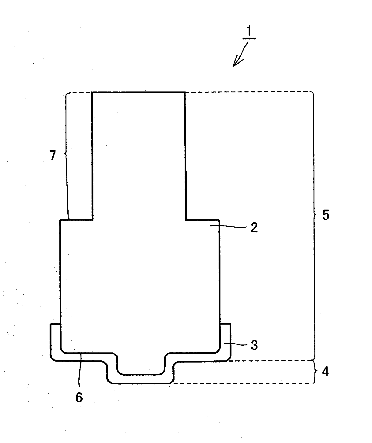
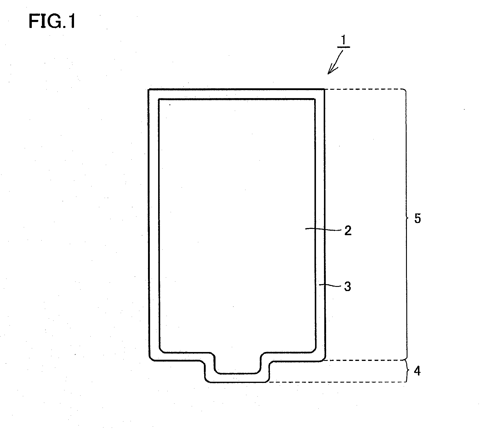
[0061]In the present example, the tool for friction stir welding shown in FIG. 1 was fabricated. The tool for friction stir welding in the present example had cylindrical portion 5 having a substantially cylindrical shape whose diameter was 10 mm and whose height was 20 mm, and probe portion 4 protruding concentrically with cylindrical portion 5 at a central portion of the tip of cylindrical portion 5. Probe portion 4 had a substantially cylindrical shape whose diameter was 4 mm and whose height was 2 mm.

[0062]In the present example, a layer having a single composition was formed as the coating layer. However, even if a layer having a composition other than the composition used in the example or two or more layers having different compositions are formed as the coating layer, or even if at least a part of the coating layer includes a ultra-multilayer structure, the similar effects can be obtained as long as at least one layer of the coating layer has a thermal permeability of 5000 J...

examples 2 to 4

[0068]In each of Examples 2 to 4 below, a tool for friction stir welding was fabricated using a method similar to that in Example 1 except that the configuration and composition of the coating layer were different from those in Example 1 as shown in Table 2 above. For example, in Example 3, Ti0.5Al0.5N having a thickness of 5 μm was formed on the base material, and thereafter, SiO0.1N0.9 having a thickness of 5 μm was formed to form the coating layer. As mentioned above, when two types of compositions are listed in the section “composition” of coating layer in Table 2, it means that a layer having a composition shown on the right side is formed, and thereafter, a layer having a composition shown on the left side is formed directly on the layer.

[0069]In Examples 3, 4, 7, and 8 in Table 2, the coating layer including two layers, i.e., a layer made of Ti0.5Al0.5N and a layer having a composition other than Ti0.5Al0.5N is formed. However, in the section “thermal permeability” in Table 2...

examples 5 to 8

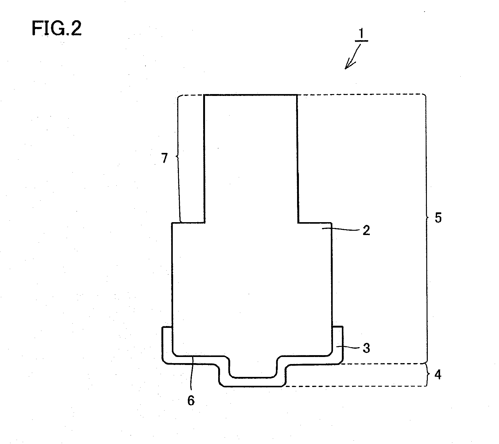
[0071]In each of Examples 5 to 8 below, the tool for friction stir welding shown in FIG. 2 was fabricated. The tool for friction stir welding in each of Examples 5 to 8 had probe portion 4 similar to that in each of Examples 1 to 4, and had chuck portion 7 such that cylindrical portion 5 was inserted into the holder. This chuck portion 7 was formed by cutting away the side surface of cylindrical portion 5 by a length of 10 mm from an upper surface of cylindrical portion 5, from opposing two directions, and had a substantially cylindrical cross-sectional shape. When chuck portion 7 is viewed from the holder side, the length of a chord formed by cutting as mentioned above was 7 mm.

[0072]A jig was attached to a portion other than probe portion 4 and shoulder portion 6, and the base material having the above-mentioned shape was mounted on a cathode arc ion plating apparatus.

[0073]Thereafter, using a method similar to that in above-mentioned Example 1, cleaning of the surface of the base...


PUM

PropertyMeasurementUnit
melting pointaaaaaaaaaa
temperatureaaaaaaaaaa

Abstract

There is provided a tool for friction stir welding, which is capable of promoting temperature rise of materials to be joined during joining to achieve friction stir welding in a short time, is excellent in heat insulating property of a coating layer, and is excellent in oxidation resistance and wear resistance. A tool for friction stir welding according to the present invention is a tool for friction stir welding including a base material and a coating layer formed on the base material, wherein the coating layer is formed of one or more layers, and at least one layer of the coating layer has a thermal permeability of 5000 J / s0.5·m2·K or less.

Description

CROSS-REFERENCE TO RELATED APPLICATIONS[0001]This application is a Continuation of U.S. patent application Ser. No. 13 / 516,396, filed Jun. 15, 2012, which is a National Stage of PCT International Application No. PCT / JP2010 / 072365, filed Dec. 13, 2010, which claims the benefit of Japan Patent Application No. 2009-286631, filed Dec. 17, 2009, all of which are incorporated by reference in their entirety.TECHNICAL FIELD[0002]The present invention relates to a tool for friction stir welding.BACKGROUND ART[0003]In 1991, a friction stir welding technique of joining metal materials such as aluminum alloys was established in the United Kingdom. This technique is for joining metal materials by pressing a cylindrical tool for friction stir welding having a small-diameter protrusion at a tip thereof against joint surfaces of the metal materials to be joined and rotating the tool for friction stir welding, generating frictional heat, and softening and plastically flowing the metal materials at a...

Claims


Application Information

Patent Timeline
Patent Type & Authority Applications(United States)
IPC IPC(8): B23K20/12
CPCB23K20/1245B23K20/1255C23C14/0641C23C14/08C23C30/00C23C30/005B23K2103/04B23K2103/12B23K2101/20B23K2103/10
Inventor MORIGUCHI, HIDEKIUTSUMI, YOSHIHARUMIYAZAKI, HIROKA
Owner SUMITOMO ELECTRIC IND LTD
Why Eureka
Try Eureka