
Apparatus for assembling blade sections

a technology for assembling blades and blades, applied in the field of wind turbines, can solve the problems of reducing economic and energetic efficiency, power output of single wind turbines, and special apparatuses for assembling such multi-section blades have not been developed, and achieve the effect of improving the quality of joints

Inactive Publication Date: 2015-05-28
YOUWINENERGY
View PDF0 Cites 1 Cited by
  • Summary
  • Abstract
  • Description
  • Claims
  • Application Information

AI Technical Summary

Benefits of technology

The patent describes an apparatus for joining blade sections that require a specific force or pressure to join them. The apparatus includes at least two movable members that can exert force or pressure on specific areas of the blade sections. This ensures a high-quality joint. The apparatus also has a resin discharge means that monitors the amount of resin being supplied and controls the supply based on this information. This ensures that the resin is being supplied in the right amount to completely fill the flow path between the blade sections, resulting in a stronger joint. Overall, this apparatus improves the joining process for blade sections.

Problems solved by technology

Due to the fact that large-scale wind turbine installations are frequently set up at remote locations, restrictions with respect to transportation of blades having a length of 50 m or more introduce a limitation on the power output of the single wind turbine and consequently decrease the economic and energetic efficiency.
Special apparatuses for assembling such multi-section blades have not been developed yet.

Method used


Image

  • Apparatus for assembling blade sections
  • Apparatus for assembling blade sections
  • Apparatus for assembling blade sections

Examples


Embodiment Construction

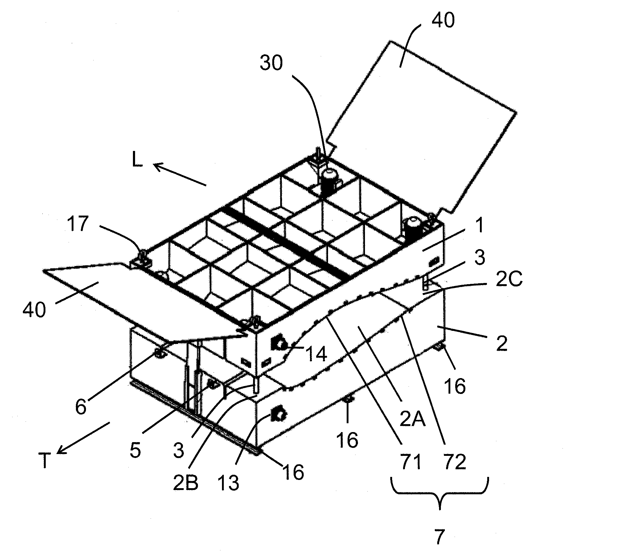
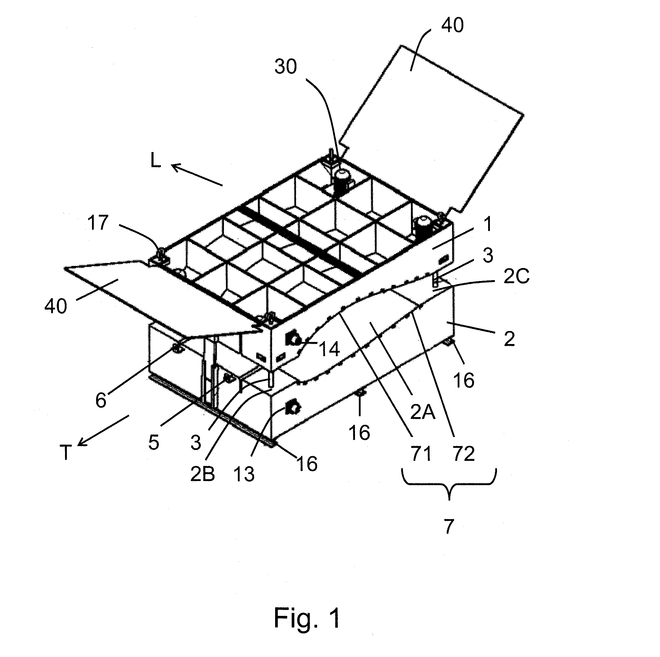
[0057]FIG. 1 shows the apparatus for assembling blade sections for forming a blade according to the embodiment. In the following, the components forming the apparatus will be explained first.

[0058]The apparatus shown in FIG. 1 comprises two members 1, 2 which are arranged in a spaced relationship. One of the members 1, 2 is arranged on top of the other of the members. In the following, a top member 1 which is arranged on top of a bottom member 2 will be defined. It is noted that this definition is only used for explaining the embodiment and does not restrict the scope as the apparatus can be used in an orientation which differs from the orientation shown in FIG. 1.

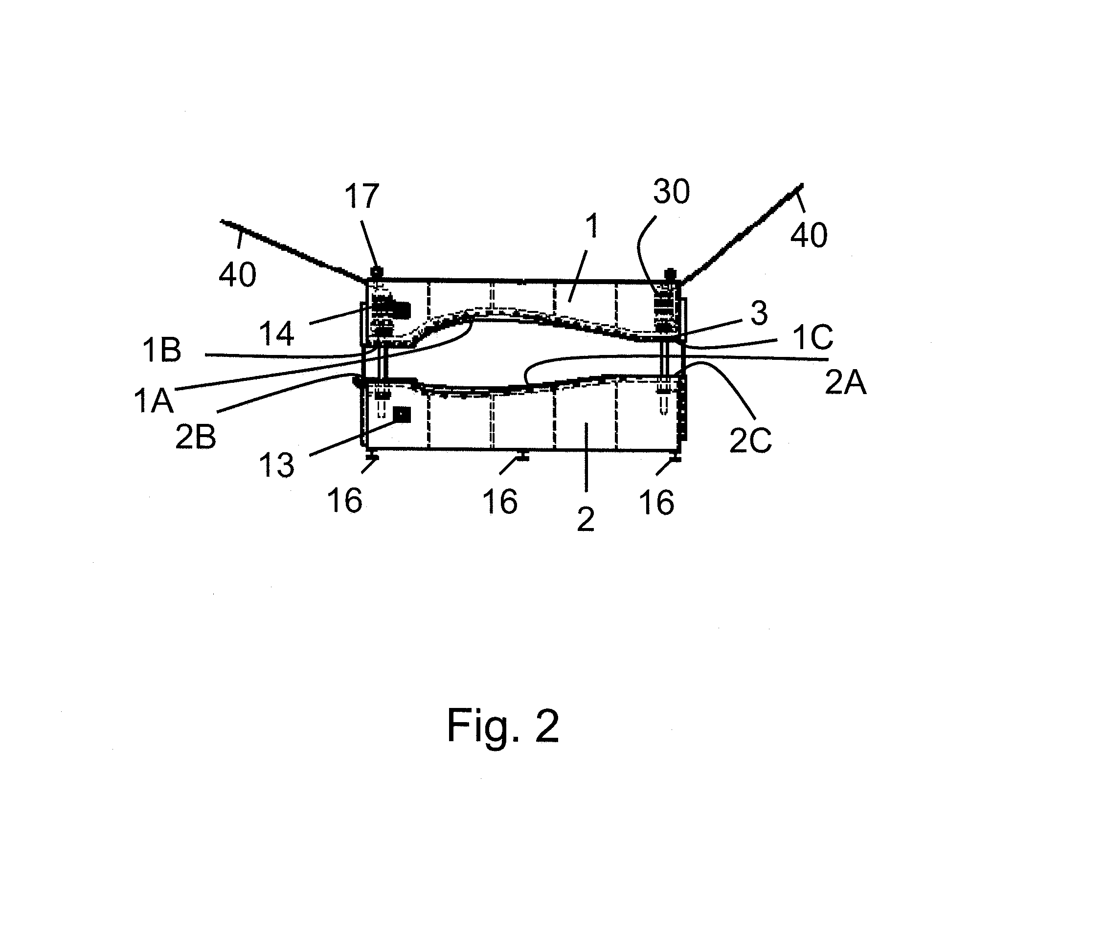
[0059]As shown in FIG. 2, the top member 1 includes a surface 1A and the bottom member includes a surface 2A. The surfaces 1A, 2A are opposed to each other in order to create a pressing space there between. The surfaces 1A, 2A are formed by sheet metal or a similar material. The surfaces 1A, 2A are provided with a specific...


PUM

PropertyMeasurementUnit
Currentaaaaaaaaaa
Digital informationaaaaaaaaaa
Temperatureaaaaaaaaaa

Abstract

An apparatus for assembling blade sections for forming a blade is provided. The apparatus comprises at least two members (1, 2) movable with respect to each other, said members having respective opposing surfaces (2A, 2B) forming a pressing space for pressing outer surfaces of preassembled blade sections in a transition between the sections.

Description

[0001]The present subject matter relates to an apparatus for assembling blade sections for forming a blade for a wind turbine rotor. In particular, the apparatus for assembling blade sections according to the present subject matter enables an advantageous operation for assembling blades for large-scale wind turbines.[0002]Further, the present subject matter relates to a method of operating the apparatus which provides a simplified and enhanced procedure for assembling blades for large-scale wind turbines.BACKGROUND[0003]In a commonly known wind turbine, a plurality of blades is mounted to a hub. The hub is connected to a generator system. The generator systemgenerates electricity based on the rotational power caused by wind energy exerted on the blades. In commonly known wind turbine installations, the hub is rotatably mounted with the axis being aligned substantially horizontally, such an installation is referred to as a horizontal axis wind turbine.[0004]In recent years, the lengt...

Claims


Application Information

Patent Timeline
IPC IPC(8): B23P15/04B29C65/00F03D80/00
CPCB23P15/04B29L2031/085B29K2101/10B29C66/95F03D1/0675F05B2240/302F05B2230/41F05B2280/6015F05B2280/701Y02E10/72Y10T29/49336Y10T29/53Y02P70/50F03D1/06F03D1/0608F03D1/0601
Inventor ROHDEN, ROLF
Owner YOUWINENERGY
Learn More