Joint head and parts installation equipment

A technology for jointing heads and components, which is applied to joints, electrical components to assemble printed circuits, electrical components, etc., and can solve problems such as insufficient parallelism of electronic components 13 circuit boards 15, inability to align in parallel, and differences in contact states

Inactive Publication Date: 2002-08-28
PANASONIC CORP
View PDF0 Cites 6 Cited by
  • Summary
  • Abstract
  • Description
  • Claims
  • Application Information

AI Technical Summary

Problems solved by technology

[0010] However, in the bonding head 1 described above, the following problem arises: when the pressing tool 10 is aligned parallel to the bonding table 16, due to the resistance of the heater 11, the wiring 17, 18 of the thermocouple 12, and the resistance of the heater 11 , The effect of the weight of the thermocouple 12 produces resistance and cannot make it fully parallel aligned
As a result, the following problems occur: when performing the bonding operation, the parallelism of the electronic component 13 with respect to the circuit board 15 is not sufficient, and the contact state of each electrode of the electronic component 13 and the circuit board 15 is different, so that it cannot be achieved at a high level. splicing quality for splicing

Method used


Image

  • Joint head and parts installation equipment
  • Joint head and parts installation equipment
  • Joint head and parts installation equipment

Examples


Embodiment Construction

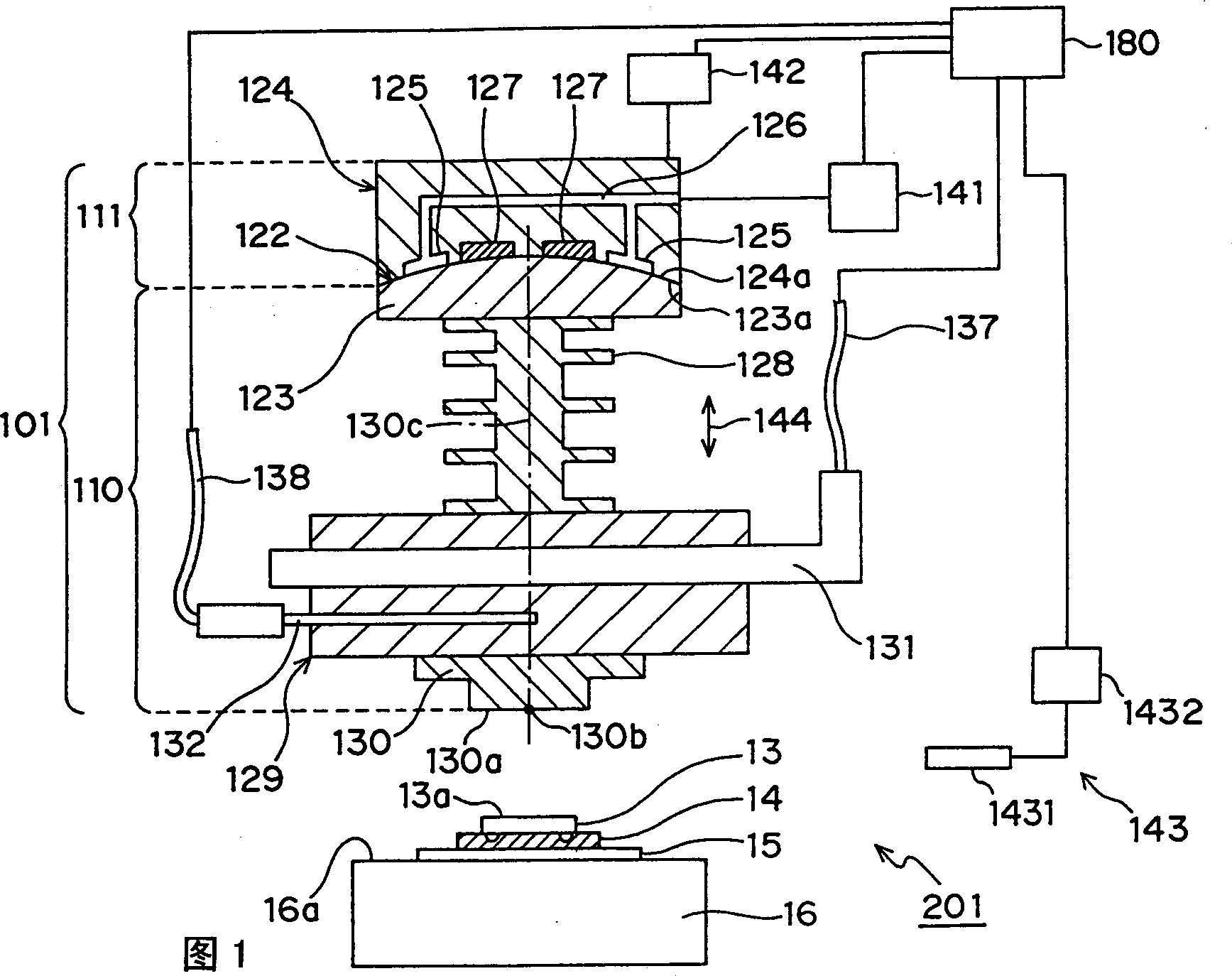
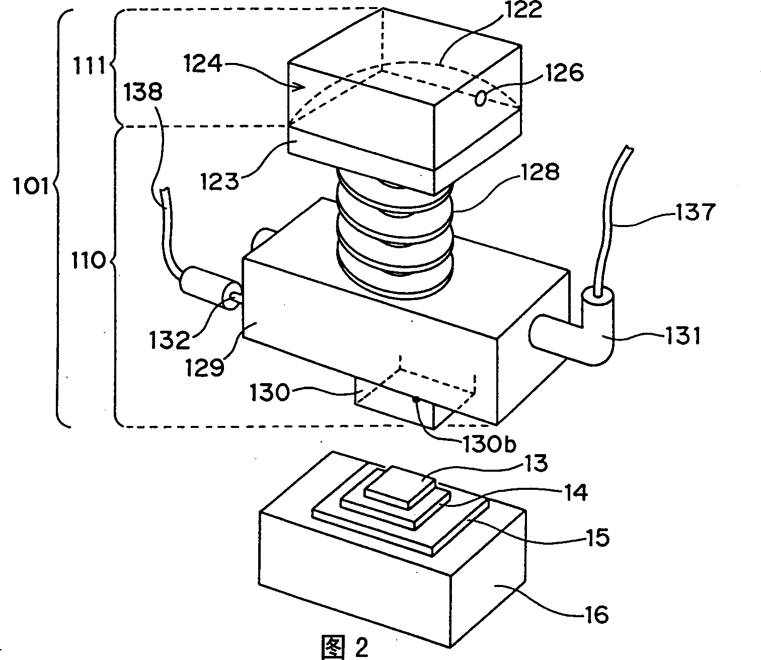
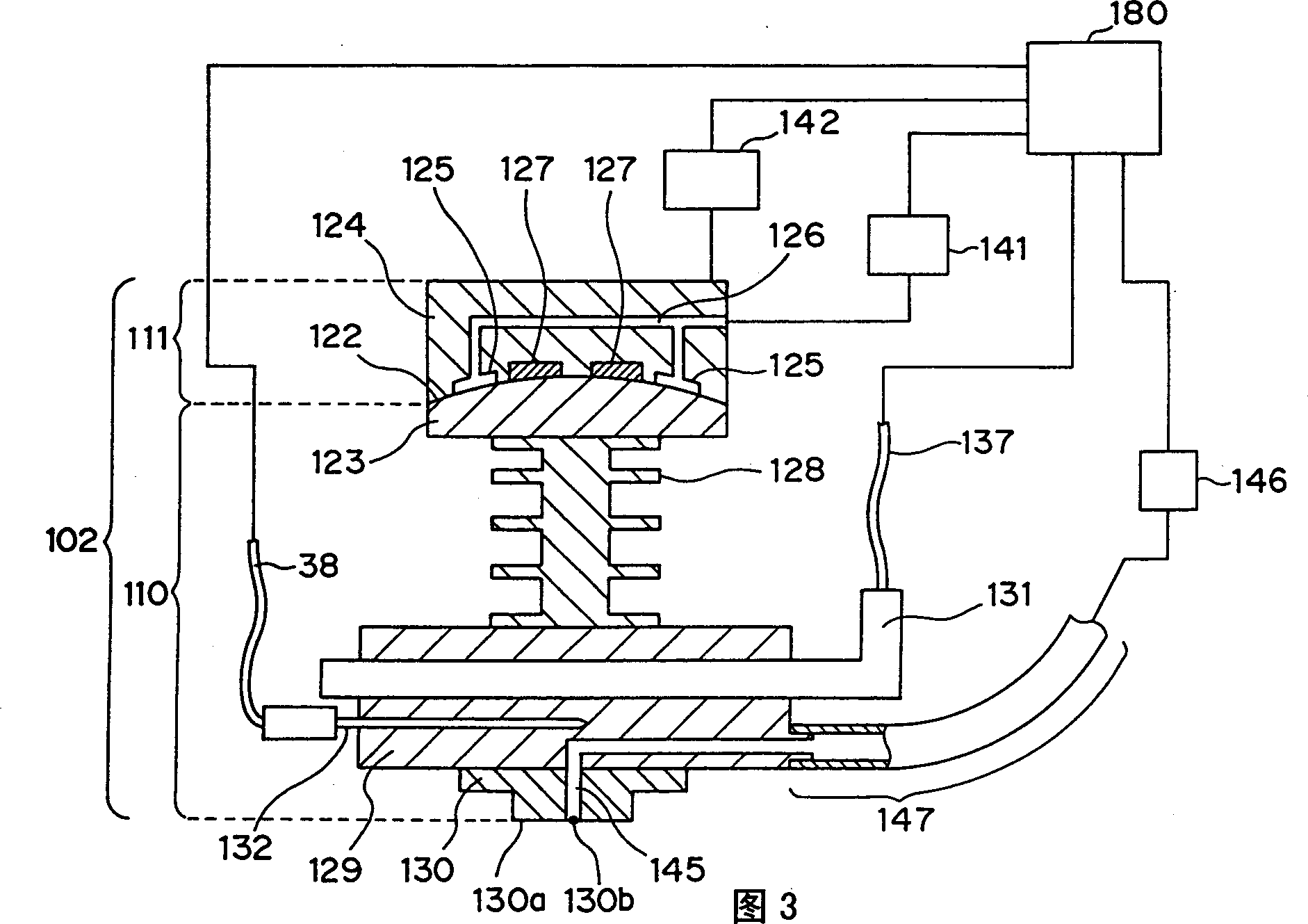
[0051] A bonding head, which is an embodiment of the present invention, and a component mounting apparatus including the bonding head will be described below with reference to the drawings. In addition, in each drawing, the same code|symbol is attached|subjected to the same component. In addition, in this specification, the so-called circuit forming body refers to circuit boards such as resin substrates, paper-phenolic substrates, ceramic substrates, glassy epoxy resin (epoxy glass) substrates, and film substrates; A circuit board such as a substrate or a multilayer substrate; a component; an object forming a circuit such as a frame or a frame. Also, in the present embodiment, a circuit board is taken as an example of a circuit forming body, and an electronic component mounted on the circuit board is taken as an example of a component.

[0052] As shown in FIGS. 1 and 2 , the bonding head 101 of this embodiment is roughly divided into a pressing portion 110 and a support port...


PUM


Abstract

A bonding head includes an inclination preventing member 129 capable of preventing the inclination of the pressing portion 110 relative to the support portion 111, and setting the pressing surface 130a and the mounting surface 16a in an approximately parallel state. Therefore, the pressing surface can be provided with a higher degree of parallelism with respect to the bonding stage 16 than conventionally, and components and circuit-formed bodies can be bonded with high bonding quality.

Description

technical field [0001] The present invention relates to a bonding head for mounting electronic components on a circuit board and a component mounting device with the bonding head. Background technique [0002] Conventionally, spherical bearings have been used as an example of parallel adjustment means for the bonding head. This spherical bearing can be adjusted in parallel by aligning the pressing tool of the bonding head with an object such as a bonding table, so parallel adjustment can be performed relatively easily. [0003] Next, an example of a bonding head using a spherical bearing in the parallel adjustment portion will be described with reference to the drawings. FIG. 9 is a perspective view of a conventional bonding head, and FIG. 10 is a cross-sectional view thereof. In FIGS. 9 and 10 , 1 is a bonding head. Reference numeral 2 denotes a spherical portion, which is formed by contacting a member 3 having a convex spherical portion and a member 4 having a concave s...

Claims


Application Information

Patent Timeline
Patent Type & Authority Applications(China)
IPC IPC(8): B25J17/02B23K20/02H05K3/34
CPCB23K20/02B23K2101/40
Inventor 细谷直人大野修治西川英信前野光男那须博
Owner PANASONIC CORP
Why Eureka
Try Eureka