Control mechanism for delay start of spinning device rotor

A technology of delay start and control mechanism, which is applied in the field of spinning machine parts, can solve problems such as the inability to remove the quality of cotton fiber yarn joints, and achieve the effect of improving quality and improving quality

Active Publication Date: 2010-12-01
ZHEJIANG RIFA TEXTILE MASCH CO LTD
View PDF0 Cites 7 Cited by
  • Summary
  • Abstract
  • Description
  • Claims
  • Application Information

AI Technical Summary

Problems solved by technology

[0003] The purpose of the present invention is to solve the technical problem that the existing semi-automatic rotor spinning machine cannot remove the damaged cotton fibers at the head of the sliver and affect the quality of the yarn joint, and to provide a spinning device that can realize Spinner Rotor Delay Start Control Mechanism for Removing Damaged Fibers

Method used


Image

  • Control mechanism for delay start of spinning device rotor
  • Control mechanism for delay start of spinning device rotor
  • Control mechanism for delay start of spinning device rotor

Examples


Embodiment 1

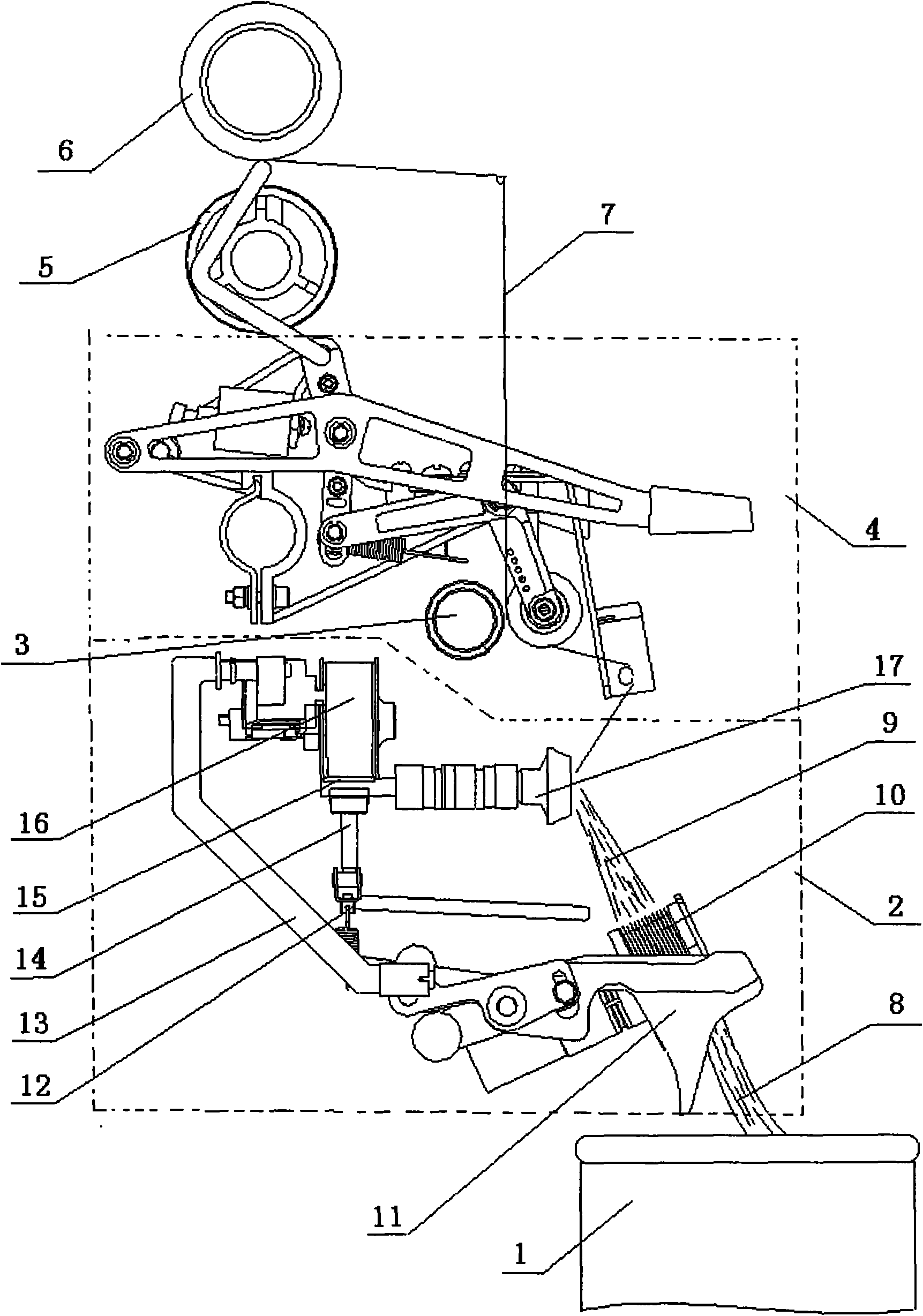
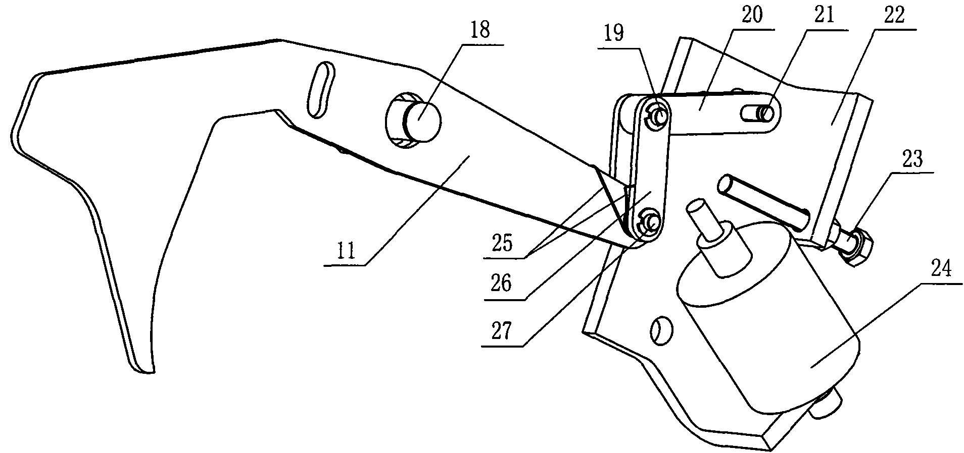
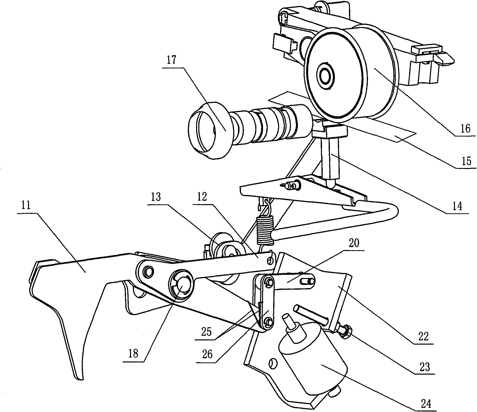
[0028] Such as Figure 2 ~ Figure 4 As shown, the present invention includes a hook pull rod 11 and a position locking device for the hook pull rod. The middle part of the hook pull rod 11 is provided with a shaft hole. The described hook pull rod position locking device includes a mounting plate 22, a torsion spring 25, and a push rod electromagnet. 24. Limiter, upper strut 20 and lower strut 26, the limiter is a limit screw 23, the lower end of upper strut 20 and the upper end of lower strut 26 are flexibly connected by the first pin shaft 19, and the lower end of lower strut 26 It is flexibly connected with the tail end of the hook pull rod 11 through the second pin shaft 27, and the upper end of the upper pole 20 is provided with a hole. Rotate around the third pin shaft 21, the limit screw 23, the third pin shaft 21 and the push rod electromagnet 24 are fixedly installed on the mounting plate 22, and the push rod electromagnet 24 and the limit screw 23 are located on the ...

Embodiment 2

[0032] Such as Figure 5 As shown, the hook pull rod position locking device according to the present invention includes a locking electromagnet 28 and a transverse hole 29 arranged at the tail end of the hook pull rod 11. The locking electromagnet 28 is in a fixed position, and the sliding iron core axis and lateral direction of the locking electromagnet 28 The centerlines of the holes 29 are in the same direction, and the sliding iron core of the locking electromagnet 28 can pass through the transverse holes 29 . When the yarn is broken, the sliding iron core of the locking electromagnet 28 penetrates into the transverse hole 29 to lock the position of the hook pull rod 11. After the damaged fiber is removed, the sliding iron core of the locking electromagnet 28 escapes from the transverse hole 29, and the hook is released. Locking of the position of the head pull rod, the hook head pull rod 11 resets and rotates, the pressure wheel 16 and the brake mechanism 14 are lowered ...

Embodiment 3

[0034] Such as Image 6 As shown, the hook rod position locking device of the present invention includes an electromagnet 30 and a sucked piece 31 arranged at the tail end of the hook pull rod 11 . The position of the electromagnet 30 is fixed and corresponding to the sucked piece 31 . When the yarn is broken, the electromagnet 30 is energized to attract the attracted block 31 to lock the position of the hook pull rod. After the damaged fibers are removed, the electromagnet 30 is powered off, and the lock on the position of the hook pull rod is released, and the hook pull rod 11 is reset. Rotate, the pinch wheel 16 and the brake mechanism 14 are descended by the pinch wheel link mechanism 13 and the brake link mechanism 12, and the delay start rotor 17 rotates, and simultaneously inserts the yarn leading end joint for spinning.


PUM


Abstract

The invention relates to a control mechanism for the delay start of a spinning device rotor, belonging to the field of spare parts of a spinning machine and solving the technical problem that the spinning joint quality of a traditional semi-automatic rotor spinning machine is influenced because damaged cotton fiber at the head of cotton silver can not be removed. The control mechanism for the delay start of the spinning device rotor comprises a hook pull rod with a shaft hole arranged in the middle and is characterized in that a hook pull rod position locking device is arranged at the tail of the hook pull rod for locking and releasing the position of the hook pull rod, and the delay start of the spinning device rotor is controlled by a pinch roller linkage mechanism and a brake linkage mechanism which are connected with the tail end of the hook pull rod so as to remove the damaged fiber at the head of the cotton silver and improve the quality of broken yarn joints.

Description

technical field [0001] The invention belongs to the field of spinning machine components, and in particular relates to a delay start control mechanism for a spinner rotor of a rotor spinning machine. Background technique [0002] Rotor spinning machine is a kind of open-end spinning equipment, such as figure 1 Shown is the spinning device of a semi-automatic rotor spinning machine, which is mainly composed of a sliver can 1, a spinning device 2, a yarn delivery mechanism 3, a semi-automatic splicing device 4, a winding shaft 5 and a yarn bobbin 6 successively. Commonly used spinning device 2 includes cotton feeding roller, carding roller 10, rotor cup 17, hook head pull rod 11, pressure roller linkage mechanism 13, rotor cup brake mechanism 14 and brake linkage mechanism 12, etc. The wheel 16 presses against the rotating shaft of the rotor cup 17 to provide power for the rotor cup high-speed rotation transmission motor. During spinning, the fan is used to inhale the spinni...

Claims


Application Information

Patent Timeline
Patent Type & Authority Applications(China)
IPC IPC(8): D01H4/12
Inventor 吕永法王幼平
Owner ZHEJIANG RIFA TEXTILE MASCH CO LTD
Why Eureka
Try Eureka