
Media transport device with vacuum-controlled positioning

Active Publication Date: 2010-08-26
XEROX CORP
View PDF15 Cites 46 Cited by
  • Summary
  • Abstract
  • Description
  • Claims
  • Application Information

AI Technical Summary

Benefits of technology

The patent describes a system for printing on paper or other materials while they move through an apparatus. A vacuum sucks the material onto the moving belt where it passes through various devices like cutters and printers. To make sure this works properly, there needs to be alignment between the opening of the vacuum chamber and the position of the material when it moves through the machine. Also, the size of the opening should match the size of the material. This helps keep the material securely attached to the belt without any leaks that could affect its quality during production.

Problems solved by technology

The technical problem addressed in this patent text needs to be identified by a senior R&D personnel who has read it through.

Method used


Image

  • Media transport device with vacuum-controlled positioning
  • Media transport device with vacuum-controlled positioning
  • Media transport device with vacuum-controlled positioning

Examples


Embodiment Construction

[0022]The embodiments of the invention and the various features and advantageous details thereof are explained more fully with reference to the non-limiting embodiments that are illustrated in the accompanying drawings and detailed in the following description.

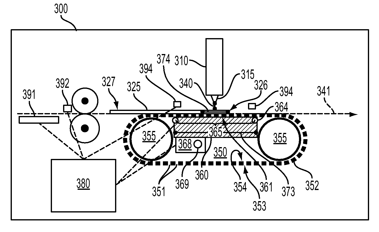
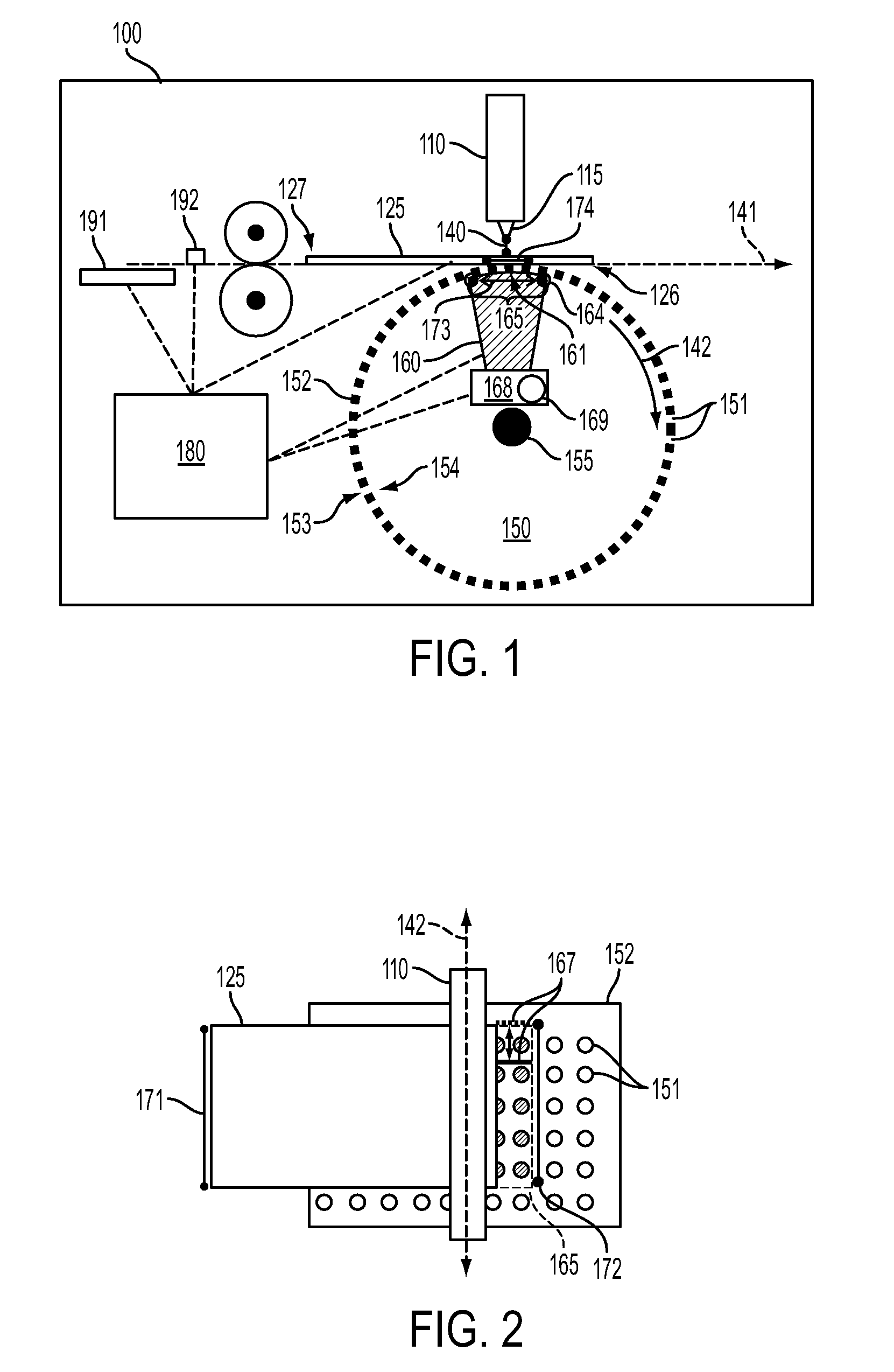
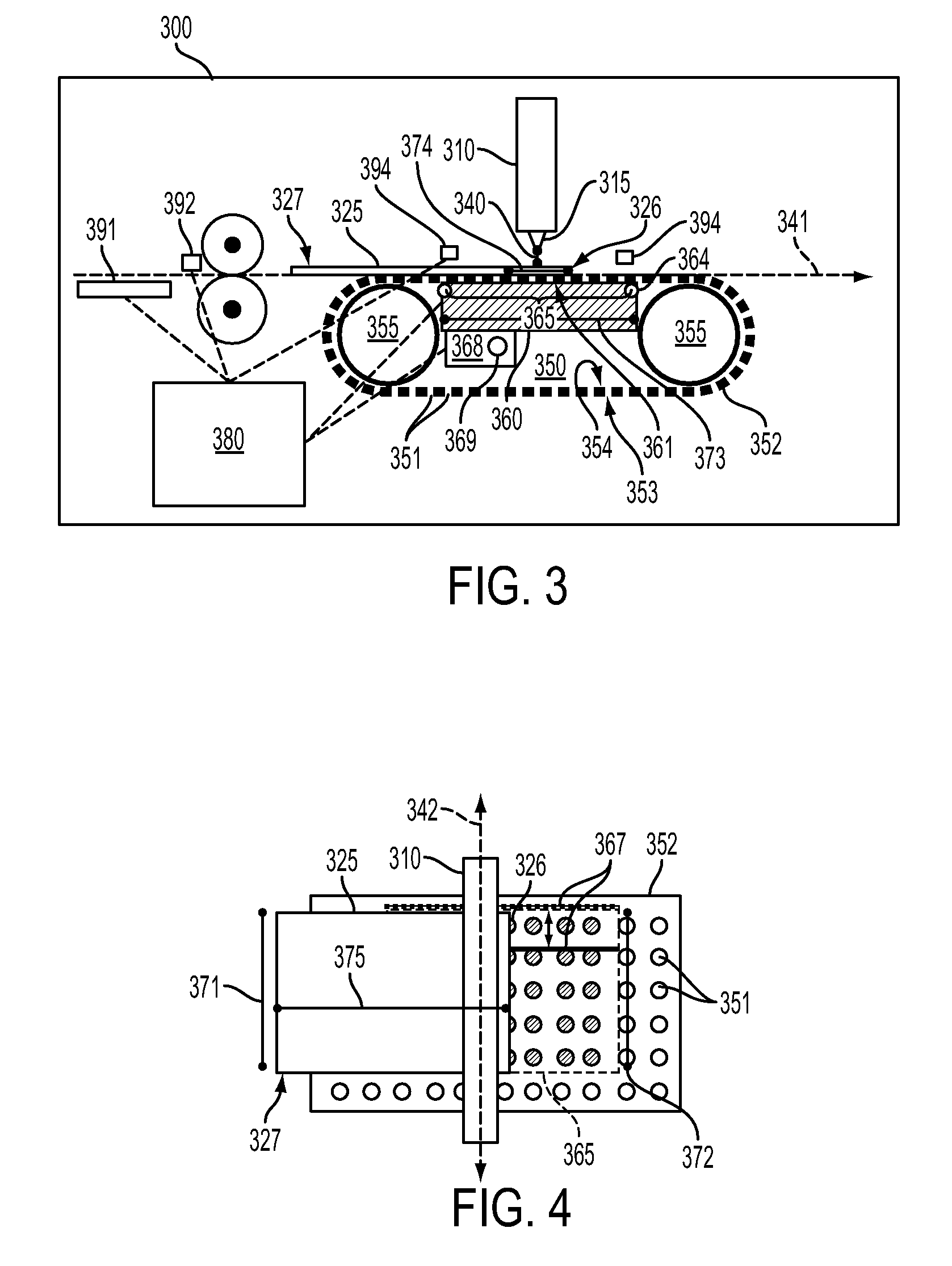
[0023]As mentioned above, for machines that incorporate print media processing devices, such as image printing devices (e.g., inkjet printing devices), image scanning devices and / or spectrophotometers, the distance separating the print medium from the key processing component of the processing device and must be uniformly and precisely maintained to prevent processing errors. For example, in an inkjet printing device (e.g., as described in detail in U.S. Pat. No. 6,779,861, issued on Aug. 24, 2004, assigned to Xerox Corporation, Norwalk, Conn. and incorporated herein its entirety by reference) the distance separating the inkjet printing head and the print medium should remain constant to avoid registration errors. In an image ...


PUM

PropertyMeasurementUnit
Weightaaaaaaaaaa
Pressureaaaaaaaaaa
Sizeaaaaaaaaaa

Abstract

Disclosed are embodiments of a machine which transports and processes print media. The machine incorporates a vacuum chamber within a print media transport device in order to maintain a print medium at a uniform predetermined distance from a print media processing device, such as an image printing device (e.g., an inkjet printer), an image scanning device, or a spectrophotometer). In one embodiment the vacuum chamber is located within a roller that transports print media past the processing device. In another embodiment the vacuum chamber is located on an opposite side of a belt that transports print media past the processing device. In each of the embodiments the size of the vacuum chamber opening, which defines the vacuum area on the transport device, and also the amount of vacuum pressure may be selectively adjusted depending upon the size and weight, respectively, of the print medium being processed.

Description


Claims


Application Information

Patent Timeline
Owner XEROX CORP
Features
  • Generate Ideas
  • Intellectual Property
  • Life Sciences
  • Materials
  • Tech Scout
  • Unparalleled Data Quality
  • Higher Quality Content
  • 60% Fewer Hallucinations
Learn More