
Negative pressure treatment system with heating and cooling provision

a treatment system and negative pressure technology, applied in the field of wound healing, can solve the problems of reducing oxygen and nutrients, affecting the healing process, and reducing the ability to fight effectively, so as to prevent vacuum leakage and reduce the loss of vacuum at the wound si

Inactive Publication Date: 2006-12-05
KCI LICENSING INC
View PDF116 Cites 271 Cited by
  • Summary
  • Abstract
  • Description
  • Claims
  • Application Information

AI Technical Summary

Benefits of technology

[0010]According to the preferred embodiment of the present invention, a heating and cooling provision is added to the previously known VAC therapy to control the local metabolic function as part of the inflammatory response. By providing localized heating in combination with the otherwise ordinary VAC therapy, the overall inflammatory response can be synergistically accelerated to produce rapid capillary occlusion and earlier initiation of the cleanup and rebuilding stages. Likewise, in the event that the attending clinician determines that the inflammatory response has been over-activated, localized cooling may be provided in combination with the VAC therapy to retard the body's inflammatory response without sacrifice of the edema control and other aspects of the otherwise provided VAC therapy.
[0012]While the heating and cooling pad may be placed inside or outside of the wound drape during the heating aspect of the present invention, it is critical that the heating and cooling pad be placed inside of the wound drape during the cooling aspect of the present invention. In this manner, condensate formation on the interior of the drape, which may cause the drape's adhesive to loosen and ultimately result in loss of vacuum at the wound site, can be minimized. In particular, placing the heating and cooling pad inside the wound drape limits the surrounding moisture content to that existing and generated within the confines of the wound site, which is minimized by the suction aspect of the VAC therapy.
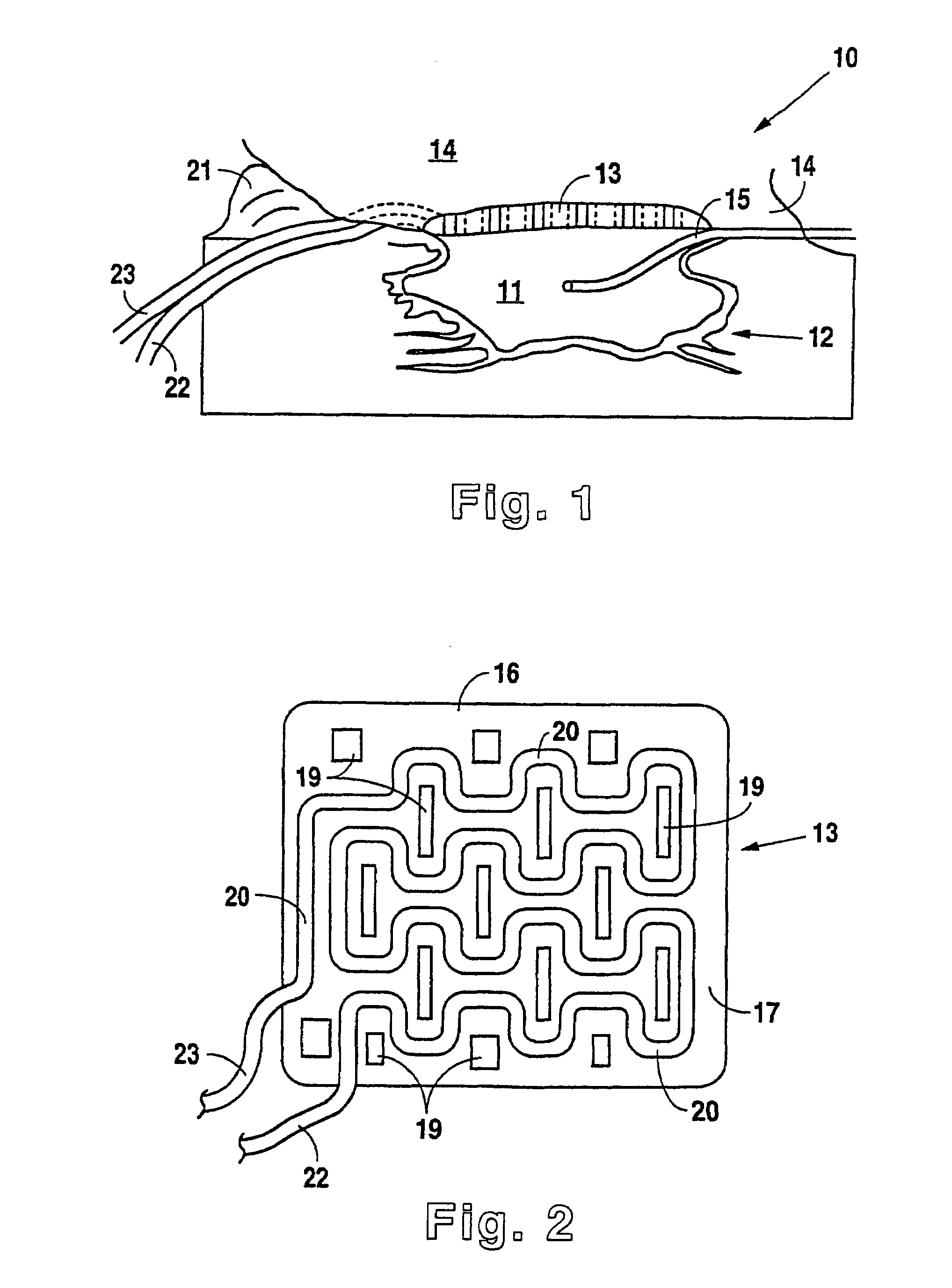
[0013]Because the cooling aspect of the present invention should be implemented in this manner and the clinician may indicate the need for cooling at any time after initiation of VAC therapy, the preferred method of the present invention comprises placing the heating and cooling pad beneath the wound drape, adjacent the foam pad and wound site, regardless of whether heating or cooling is initially indicated. Upon placement of the pad, the wound drape is firmly adhered about the supply tube and drainage tube to prevent vacuum leakage.

Problems solved by technology

Unfortunately, this process is hampered when a wound is large or has become infected.
Without sufficient blood flow, the epithelial and subcutaneous tissues surrounding the wound not only receive diminished oxygen and nutrients, but are also less able to successfully fight bacterial infection and thus are less able to naturally close the wound.
Although still widely practiced and often effective, such mechanical closure techniques suffer a major disadvantage in that they produce tension on the skin tissue adjacent the wound.
In particular, the tensile force required in order to achieve closure using sutures or staples causes very high localized stresses at the suture or staple insertion point.
These stresses commonly result in the rupture of the tissue at the insertion points, which can eventually cause wound dehiscence and additional tissue loss.
Additionally, some wounds harden and inflame to such a degree due to infection that closure by stapling or suturing is not feasible.
Wounds not reparable by suturing or stapling generally require prolonged hospitalization, with its attendant high cost, and major surgical procedures, such as grafts of surrounding tissues.
While VAC therapy has been highly successful in the promotion of wound closure, healing many wounds previously thought largely untreatable, some difficulty remains.
Because the inflammatory process is very unique to the individual patient, even the addition of VAC therapy does not result in a fast enough response for closure of some wounds, especially when applied during the occlusion and initial cleanup and rebuilding stages.
Additionally, and again at least partially attributable to the variance between patients, it is possible that a properly initiated inflammatory response may be taken too far, resulting in edema and pain.

Method used


Image

  • Negative pressure treatment system with heating and cooling provision
  • Negative pressure treatment system with heating and cooling provision

Examples


Embodiment Construction

[0018]Although those of ordinary skill in the art will readily recognize many alternative embodiments, especially in light of the illustrations provided herein, this detailed description is exemplary of the preferred embodiment of the present invention—a vacuum assisted closure system with heating and cooling provision, the scope of which is limited only by the claims appended hereto.

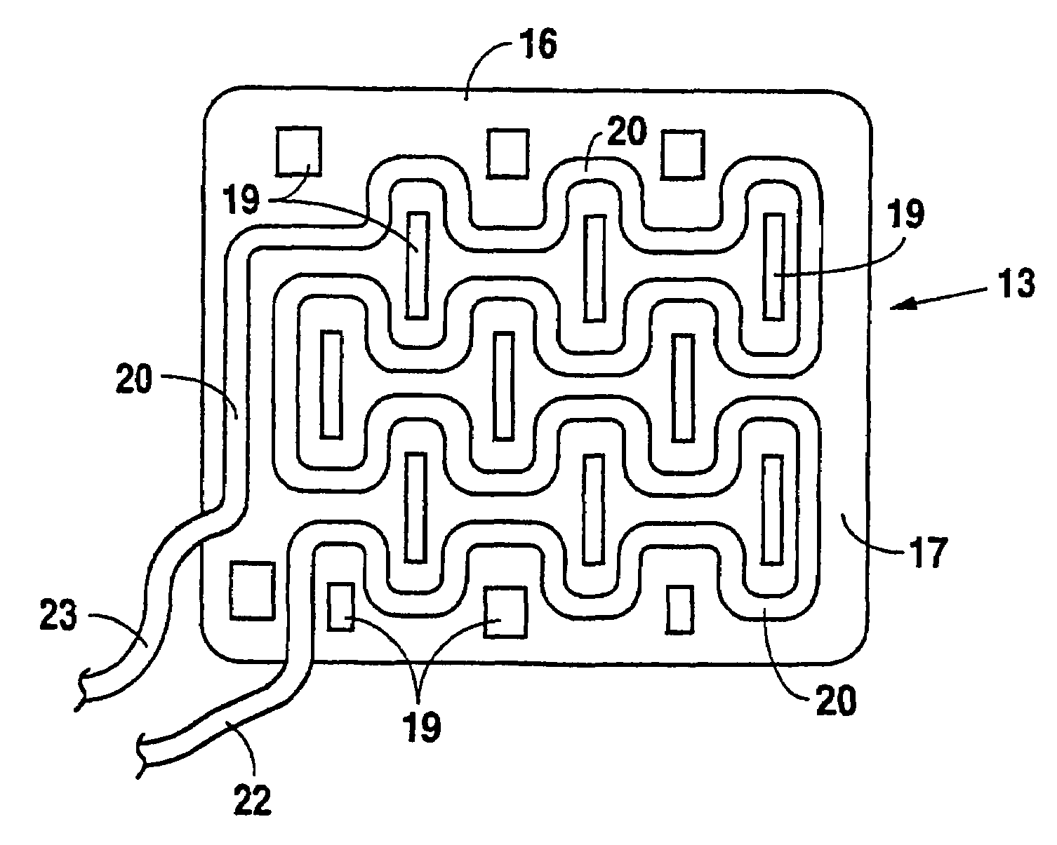
[0019]Referring now to the figures, the present invention 10 is shown to generally comprise a foam pad 11 for insertion substantially into a wound site 12, a heating and cooling pad 13 for application over the wound site 12 and a wound drape 14 for sealing enclosure of the foam pad 11 and the heating and cooling pad 13 at the wound site 12. According to the invention, the foam pad 11 is placed in fluid communication with a vacuum source for promotion of fluid drainage while warm or cool fluid is circulated through the heating and cooling pad 13 for the controlled acceleration or retardation, respectivel...


PUM


Abstract

A method, and apparatus (10) for the controlled acceleration, and / or retardation of the body's inflammatory response generally comprises a foam pad (11) for insertion substantially into a wound site, a heating, a cooling pad (13) for application over the wound site (12), a wound drape (14) or sealing enclosure of the foam pad (11), the heating, and cooling pad (13) at wound site (12). The foam pad (11) is placed in fluid communication with a vacuum source for promotion of the controlled acceleration or retardation of the body's inflammatory response. The heating, and cooling provision controls the local metabolic function as part of the inflammatory response.

Description

RELATED APPLICATION[0001]This application claims priority to United States provisional patent application Ser. No. 60 / 127,596 entitled VACUUM ASSISTED CLOSURE SYSTEM WITH HEATING AND COOLING PROVISION filed Apr. 2, 1999. By this reference, the full disclosure, including the drawings, of U.S. provisional patent application Ser. No. 60 / 127,596 is incorporated herein.TECHNICAL FIELD[0002]The present invention relates to the healing of wounds. More specifically, the present invention relates to the vacuum assisted closure of wounds wherein localized heating or cooling is used to accelerate or retard the metabolic function of the inflammatory system in order to facilitate wound healing.BACKGROUND ART[0003]Wound closure involves the inward migration of epithelial and subcutaneous tissue adjacent the wound. This migration is ordinarily assisted through the inflammatory process, whereby blood flow is increased and various functional cell types are activated. Through the inflammatory process...

Claims


Application Information

Patent Timeline
Patent Type & Authority Patents(United States)
IPC IPC(8): A61M1/00A61M35/00A61F7/02A61D1/00A61F7/00A61F7/10A61F13/00
CPCA61F7/10A61F13/00068A61F7/0085A61M1/0088A61F13/069A61F2007/0056A61F2007/0063A61F2013/00157A61F2013/00174A61F2013/00412A61F2013/00519A61F2013/00536A61F2013/0054A61F2013/0074A61M2205/3606A61M2205/366A61M1/90A61M1/915A61F13/05
Inventor HANNIGAN, RAYMOND R.LEININGER, JAMES R.BILTZ, JR., CHARLES I.DILAZZARO, FRANKFASHEK, CHRISTOPHERSCHROEDER, WAYNE J.JOHNSON, ROYCE W.
Owner KCI LICENSING INC
Learn More