X-ray generating tube, x-ray generating apparatus, x-ray imaging system, and anode used therefor

a technology of generating apparatus and generating tube, which is applied in the direction of x-ray tube target material, x-ray tube target, convertor, etc., can solve the problems of reduced tube current, reduced mean free path of electrons in the atmosphere in and sometimes caused vacuum leakage, so as to increase the durability of the x-ray generating tube and inhibit the effect of vacuum leakag

Active Publication Date: 2016-01-21
CANON KK
View PDF3 Cites 4 Cited by
  • Summary
  • Abstract
  • Description
  • Claims
  • Application Information

AI Technical Summary

Benefits of technology

[0008]It is an object of the present invention to inhibit vacuum leakage from a bonding material for hermetically bonding a target to a surrounding member due to a crack that develops because of a difference in coefficient of thermal expansion between the target and the bonding material, and to increase durability of an X-ray generating tube, and by extension, an X-ray generating apparatus and an X-ray imaging system, and an anode therein.

Problems solved by technology

That is, as X-ray generating operation and X-ray generation stop operation are repeated, vacuum leakage is sometimes caused.
When such vacuum leakage is caused, a problem arises that a mean free path of electrons in the atmosphere in the X-ray generating tube is reduced, the tube current is reduced, and the X-ray output is reduced.

Method used


Image

  • X-ray generating tube, x-ray generating apparatus, x-ray imaging system, and anode used therefor
  • X-ray generating tube, x-ray generating apparatus, x-ray imaging system, and anode used therefor
  • X-ray generating tube, x-ray generating apparatus, x-ray imaging system, and anode used therefor

Examples


first embodiment

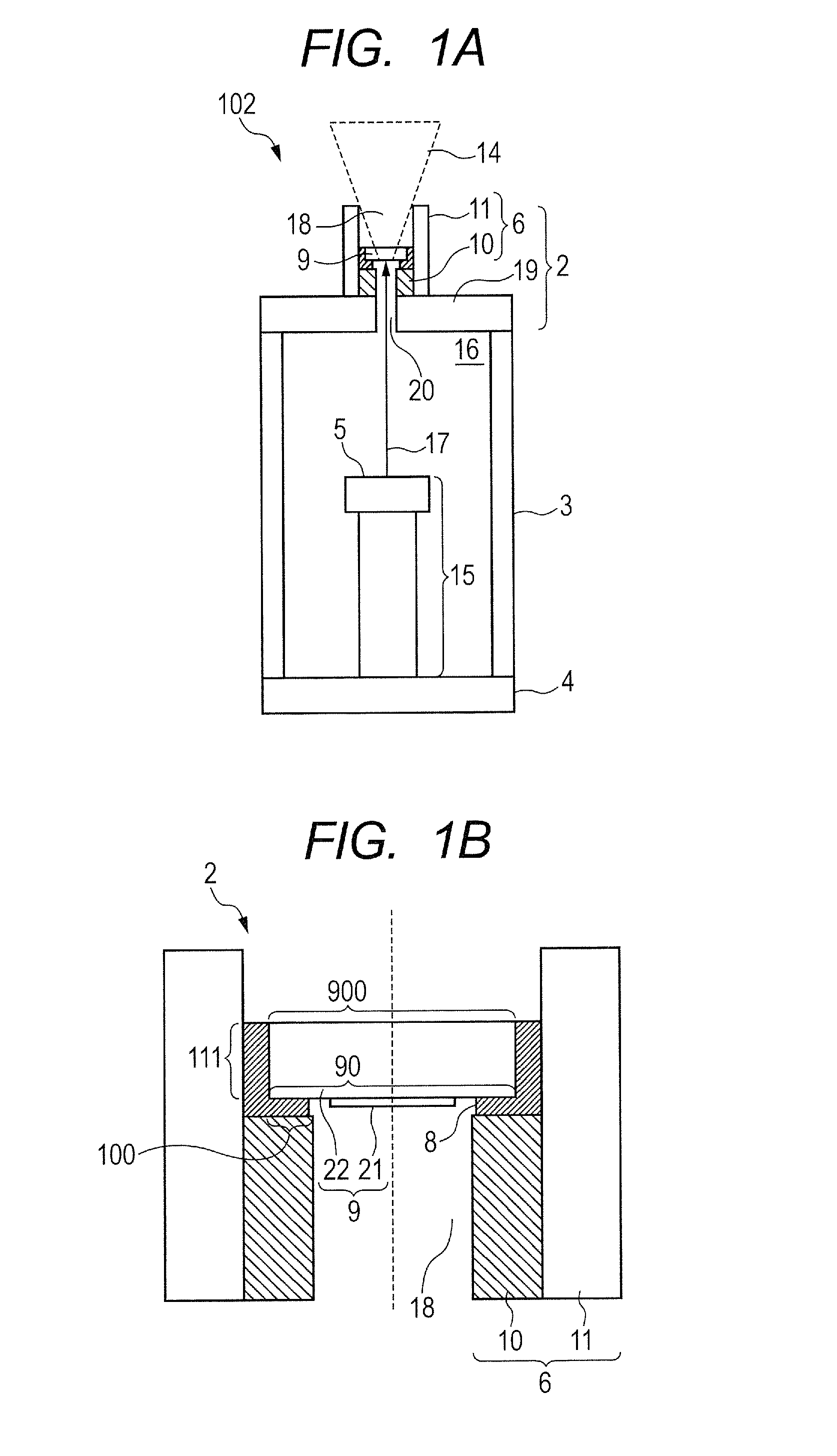
[0061]A basic form of the anode for the X-ray generating tube according to a first embodiment of the present invention is described with reference to FIG. 1B and partly with reference to FIG. 1A.

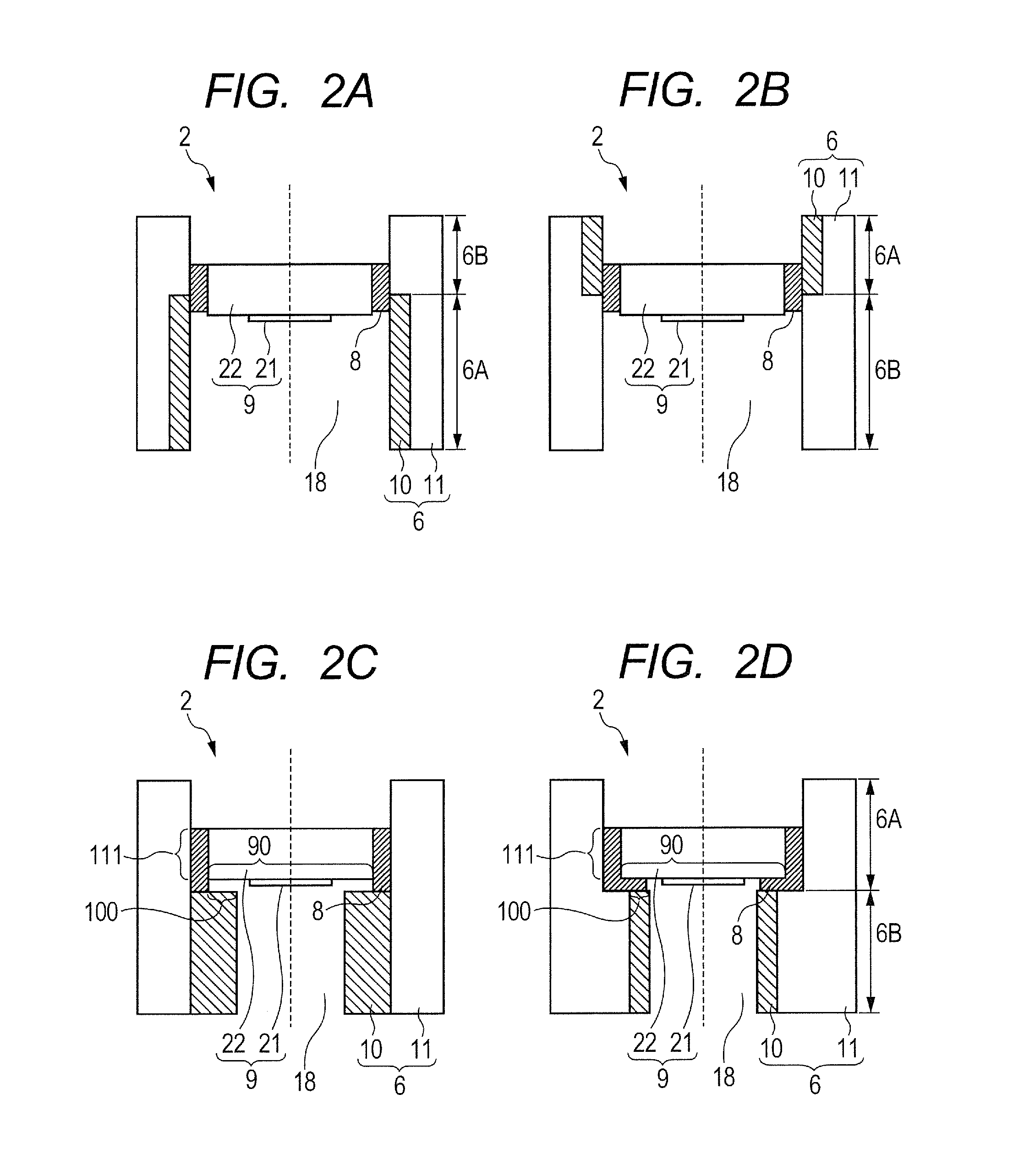
[0062]In the anode 2 according to the first embodiment, the anode member 6 includes a first metal tube 10 and a second metal tube 11. A peripheral portion of the target 9 is bonded to the anode member 6 via the bonding material 8 arranged so as to extend over the first metal tube 10 and the second metal tube 11. The second metal tube 11 has a coefficient of thermal expansion that is larger than that of the first metal tube 10. Further, the target 9 is bonded to an inside of the opening 18 in the anode member 6.

[0063]Further, the first metal tube 10 is arranged inside the second metal tube 11, and an inner surface of the second metal tube 11 and an outer surface of the first metal tube 10 are connected to each other at a portion in a tube axial direction of the second metal tube 11 so that th...

second embodiment

Anode

[0078]As illustrated in FIG. 4, in the anode according to a second embodiment of the present invention, in addition to the first metal tube 10 and the second metal tube 11, a third metal tube 12 having a coefficient of thermal expansion that is smaller than that of the second metal tube 11 is used. Further, the peripheral portion of the target 9 is bonded to the anode member 6 via the bonding material 8 that is arranged so as to extend over the first metal tube 10, the second metal tube 11, and the third metal tube 12. Specifically, under a state in which the inner surface of the second metal tube 11 has a region that is not covered with the first metal tube 10, the first metal tube 10 and the third metal tube 12 are, in series, fit into the second metal tube 11, with the third metal tube 12 being on the front end side of the second metal tube 11. There is a gap between the first metal tube 10 and the third metal tube 12, and, in the gap, the inner surface of an intermediate po...


PUM

PropertyMeasurementUnit
melting pointaaaaaaaaaa
melting pointsaaaaaaaaaa
atomic numberaaaaaaaaaa

Abstract

An anode member includes a first metal tube and a second metal tube having a coefficient of thermal expansion that is larger than that of the first metal tube. A peripheral portion of a target is bonded to the anode member via a bonding material that is arranged so as to extend over the first metal tube and the second metal tube.

Description

BACKGROUND OF THE INVENTION[0001]1. Field of the Invention[0002]The present invention relates to a transmission X-ray generating tube, an X-ray generating apparatus, and an X-ray imaging system with an anode, and an anode used therefor, the anode including a target for generating an X-ray through irradiation of an electron beam and a tubular anode member with an opening for holding the target.[0003]2. Description of the Related Art[0004]A transmission X-ray generating tube including a transmission target is known. The transmission target uses an X-ray emitted from a side thereof, which is opposite to a side, on which an electron beam enters the target. The transmission X-ray generating tube may include a target made of diamond as an end window of the X-ray generating tube. Such a transmission X-ray generating tube has advantageous features in that a radiation angle can become wider, heat dissipation performance can become higher, and an X-ray generating apparatus can be downsized. T...

Claims


Application Information

Patent Timeline
Patent Type & Authority Applications(United States)
IPC IPC(8): H01J35/08G01N23/04H01J35/02
CPCH01J35/08H01J2235/081G01N23/04H01J35/025H01J35/108H01J35/12H01J35/112H01J35/116
Inventor OHASHI, YASUOUEDA, KAZUYUKI
Owner CANON KK
Why Eureka
Try Eureka