Volume scanning three-dimensional floating image display device

a technology of image display device and volume scanning, which is applied in the direction of optics, instruments, electrical equipment, etc., can solve problems such as eye fatigu

Active Publication Date: 2010-08-26
NAT INST OF INFORMATION & COMM TECH
View PDF3 Cites 24 Cited by
  • Summary
  • Abstract
  • Description
  • Claims
  • Application Information

AI Technical Summary

Benefits of technology

[0010]One type of real mirror image forming optical system suitable for use in the present invention is a dihedral corner reflector array, having a large number of dihedral corner reflectors consisting of two mutually perpendicular specular surfaces that are perpendicular to a given optical device plane, arranged along that optical device plane, in which case that optical device plane becomes the above-mentioned symmetry surface. In this case, when the light emitted from the object to be projected passes through the optical device plane, it will be reflected once each on the two specular surfaces of each dihedral corner reflector, resulting in the component parallel to the optical device plane being reflected retroreflectively, so a real mirror image will be formed at a planar symmetric position with respect to the optical device plane. In other words, for the observer the real mirror image of the image, that is, a three-dimensional floating image, formed by being reflected from dihedral corner reflectors having their internal angles facing the observer, becomes visible.

Problems solved by technology

Many of the stereoscopic display devices currently being commercialized use only binocular disparity among the effects of stereoscopy, and because of this, problems arise due to such technical issues as focusing and convergence control, and the fatigue of the eyes when viewing for a long time; thus it is desirable to develop a more easily used technology.

Method used


Image

  • Volume scanning three-dimensional floating image display device
  • Volume scanning three-dimensional floating image display device
  • Volume scanning three-dimensional floating image display device

Examples


first embodiment

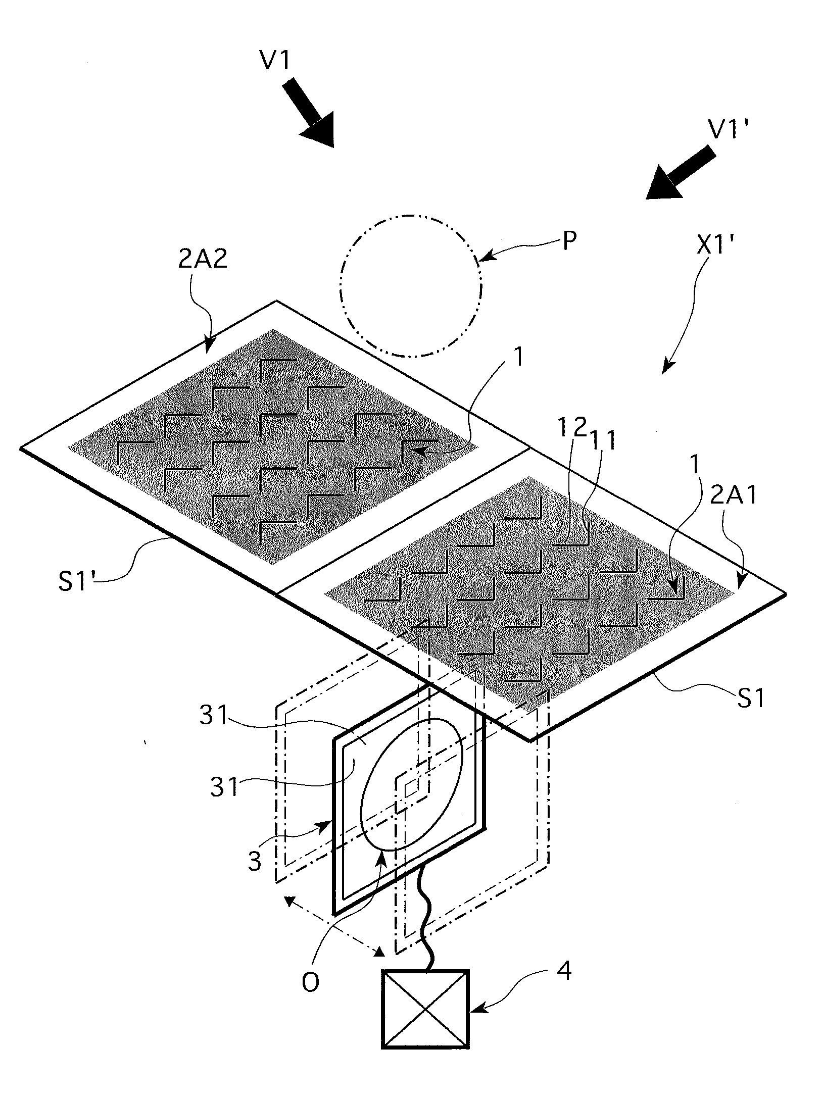
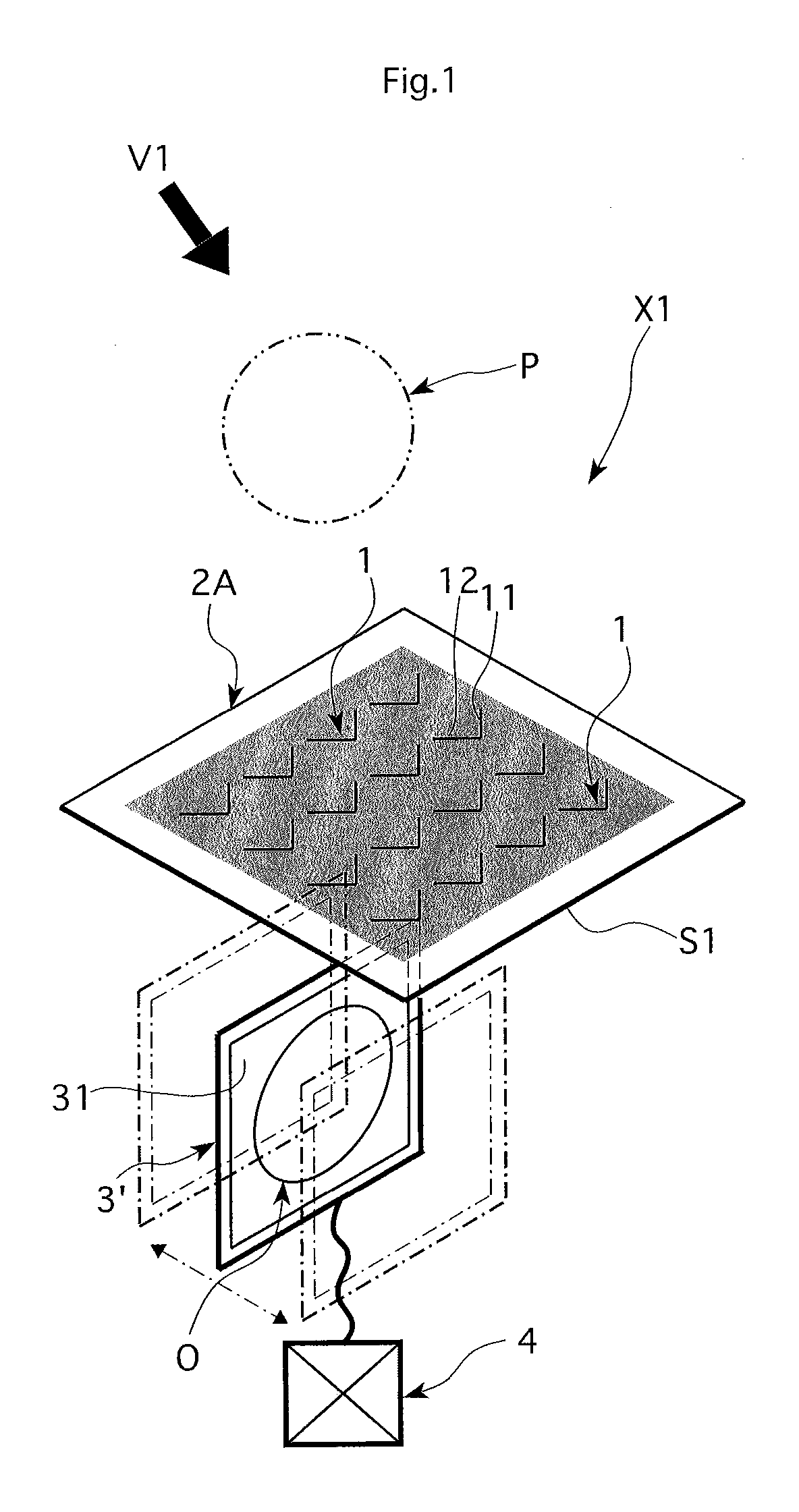
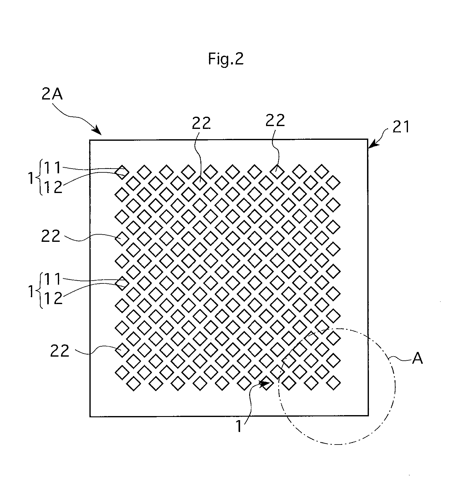
[0042]In the following, the first embodiment of the invention is described referring to FIGS. 1 through 7. The volume scanning three-dimensional floating image display X1 (in the following abbreviated as ‘three-dimensional floating image display device’) of the present embodiment is, as shown in FIG. 1, equipped with a real mirror image forming optical system 2 composed of a large number of dihedral corner reflectors 1 (in the following abbreviated as ‘dihedral corner reflector array’) as one type of a real mirror image forming optical system, and with a display 3 having a display surface 31 showing images, and further with an actuator means 4 capable of moving display 3 in a three-dimensional motion. In other words, the successively appearing images O on the display surface 31 of the moving display 3, will be the objects to be projected as real images of mirror images (real mirror images) by the dihedral corner reflector array 2A of the present embodiment, thus forming the origin f...

second embodiment

[0059]Next the second embodiment of the present invention is described referring to FIGS. 9 through 12. Pertaining to this embodiment, in the three-dimensional floating image display device X2 the real mirror image forming optical system is changed from the dihedral corner reflector array 2A used in the above-mentioned first embodiment to the real mirror image forming optical system 2B that is configured with a half-mirror 5 and a retroreflector array 6. The configuration of the display 3 and the actuator means 4 is similar to the case of the first embodiment. The real mirror image forming optical system 2B used in the present embodiment, as shown in FIG. 9, has the half-mirror surface 51 of the half-mirror 5 as the symmetry surface S2, and the images O shown in the display surface 31 of the display 3 located in the space under the half-mirror surface 51 will be reflected from the half-mirror surface 51, then returned in the incident direction by being recursively reflected from the...

third embodiment

[0067]Next the third embodiment of the present invention is described referring to FIGS. 13 and 14. Pertaining to this embodiment, the three-dimensional floating image display device X3 uses an afocal lens array 2C as the real mirror image forming optical system, while the configuration of the display 3 and the actuator means 4 is similar to the case of the first embodiment, which has arranged the display 3 parallel to the symmetry surface (see FIG. 7). This afocal lens array 2C is, as shown in FIG. 14, constructed by arranging a large number of afocal lenses 7 along an optical device plane S3. Specifically, the afocal lens 7 is constructed from two lenses 71 and 72 that share a common optical axis g that is perpendicular to the optical device plane S3, and are placed at the distance of their focal distances fs and fe. In this example, convex lenses are used for both lenses 71 and 72. That way, the incident light rays entering lens 71 from one side of the optical device plane S3 wil...


PUM


Abstract

A volume scanning three-dimensional floating image display is constructed from a real mirror image forming optical system capable of forming the real mirror image of an object to be projected in a planar symmetric position with respect to a symmetry surface, and a display located under the symmetry surface showing images that serve as the object to be projected, and an actuator means capable of moving the display in a direction with a component perpendicular to the display surface, so by changing the displayed image synchronously with the motion of the display, the real mirror image of that image will be formed in the space on the other side of the symmetry surface as a three-dimensional floating image.

Description

FIELD OF THE INVENTION[0001]The present invention is related to an optical system capable of displaying three-dimensional volume scanning floating images.BACKGROUND OF THE INVENTION[0002]Three-dimensional imaging technology has been developing in recent years. Many of the stereoscopic display devices currently being commercialized use only binocular disparity among the effects of stereoscopy, and because of this, problems arise due to such technical issues as focusing and convergence control, and the fatigue of the eyes when viewing for a long time; thus it is desirable to develop a more easily used technology. For example, in one proposed volume scanning three-dimensional method (see Non-Patent Reference 1), assuming the use convex lenses or concave mirrors as imaging optics, by arranging a two-dimensional high-speed display in a position tilted to the optical axis of the optical system, then moving the two-dimensional image that is tilted to the optical axis of the optical system ...

Claims


Application Information

Patent Timeline
Patent Type & Authority Applications(United States)
IPC IPC(8): H04N13/04
CPCG02B27/2292G02B5/136G02B30/56
Inventor MAEKAWA, SATOSHI
Owner NAT INST OF INFORMATION & COMM TECH
Why Eureka
Try Eureka