Rotary cutting tool with chip breaker pattern

a cutting tool and chip breaker technology, applied in the field of rotary cutting tools, can solve the problems of excessive wear, poor cutting action, and use of any of the conventional rotary cutting tools described

Active Publication Date: 2010-08-26
KENNAMETAL INC
View PDF16 Cites 39 Cited by
  • Summary
  • Abstract
  • Description
  • Claims
  • Application Information

AI Technical Summary

Benefits of technology

[0005]In one aspect of the invention, a rotary cutting tool with a longitudinal axis comprises a shank portion; a cutting portion extending from the shank portion to a cutting tip, the cutting portion having a length of cut, and a plurality of blades separated by flutes extending along the length of cut, each of the blades including a leading face, a trailing face, a land surface extending between the leading face and the trailing face, and a cutting edge at the intersection between the leading face and the land surface; and a plurality of chip-breaking features disposed in the land surface of each blade in a chip breaker pattern that extends along the length of cut. The chip breaker pattern is such that the chip-breaking features disposed in the land surface of one blade is located between the chip-breaking features disposed in the land surface of immediately adjacent blades.
[0006]In another aspect of the invention, a rotary cutting tool with a longitudinal axis comprises a shank portion; a cutting portion extending from the shank portion to a cutting tip, the cutting portion having a length of cut, and a plurality of blades separated by flutes extending along the length of cut, each of the blades including a leading face, a trailing face, a land surface extending between the leading face and the trailing face, and a cutting edge at the intersection between the leading face and the...

Problems solved by technology

There are several inherent problems in the use of any of the conventional rotary cutting tools described above.
Generally, these problems manifest themselves in excessive wear and relatively poor cutting actions, or both, due to the fact that the entire length of the cutting edge may be applied to the workpiece at the same...

Method used


Image

  • Rotary cutting tool with chip breaker pattern
  • Rotary cutting tool with chip breaker pattern
  • Rotary cutting tool with chip breaker pattern

Examples


Embodiment Construction

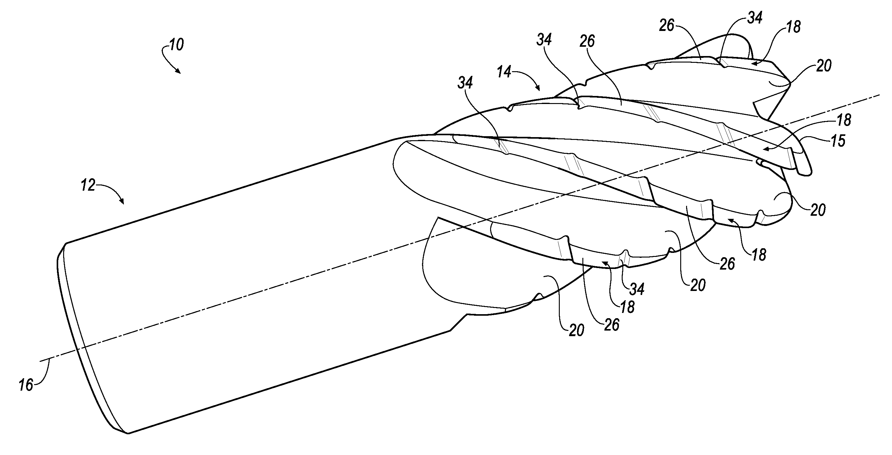
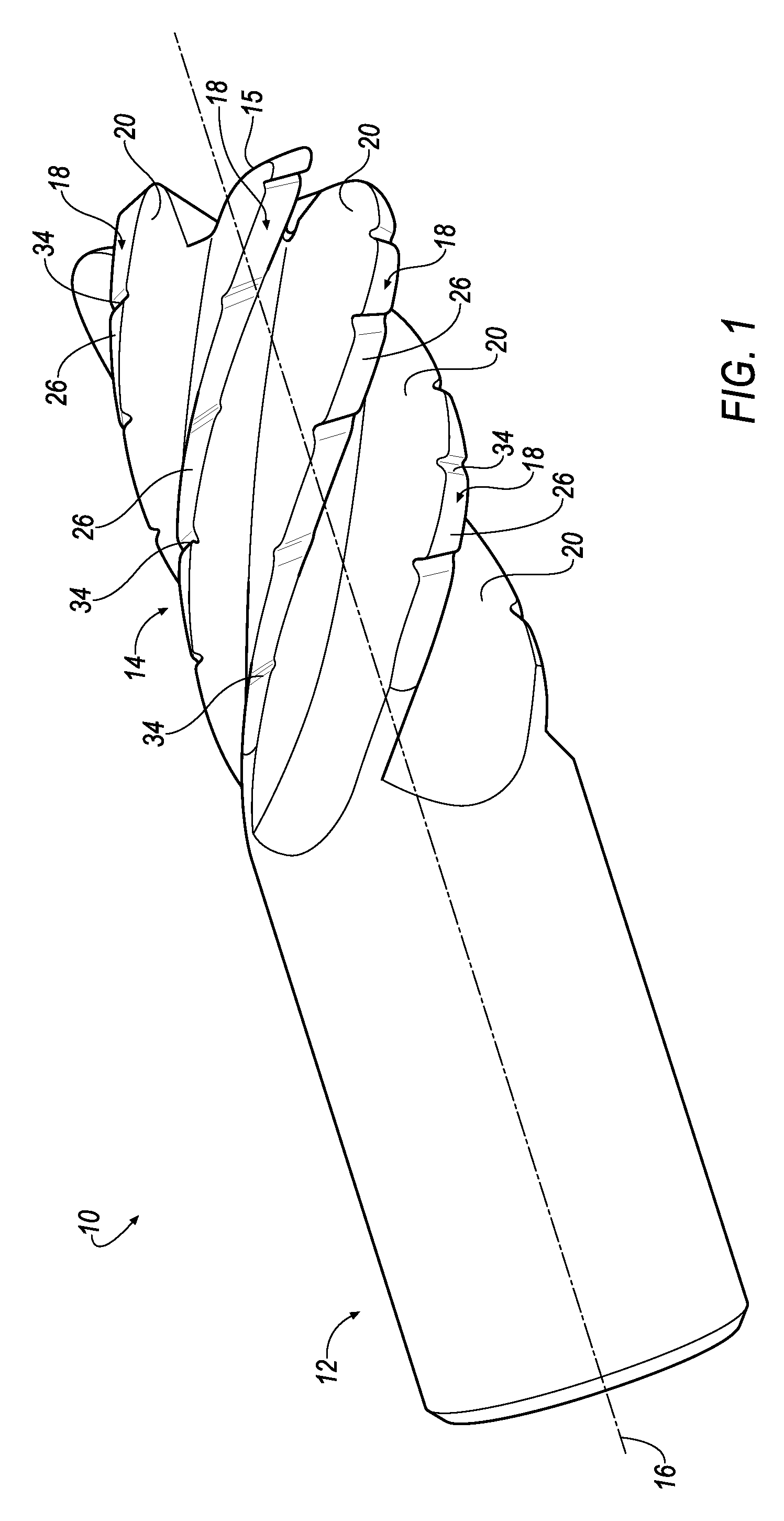
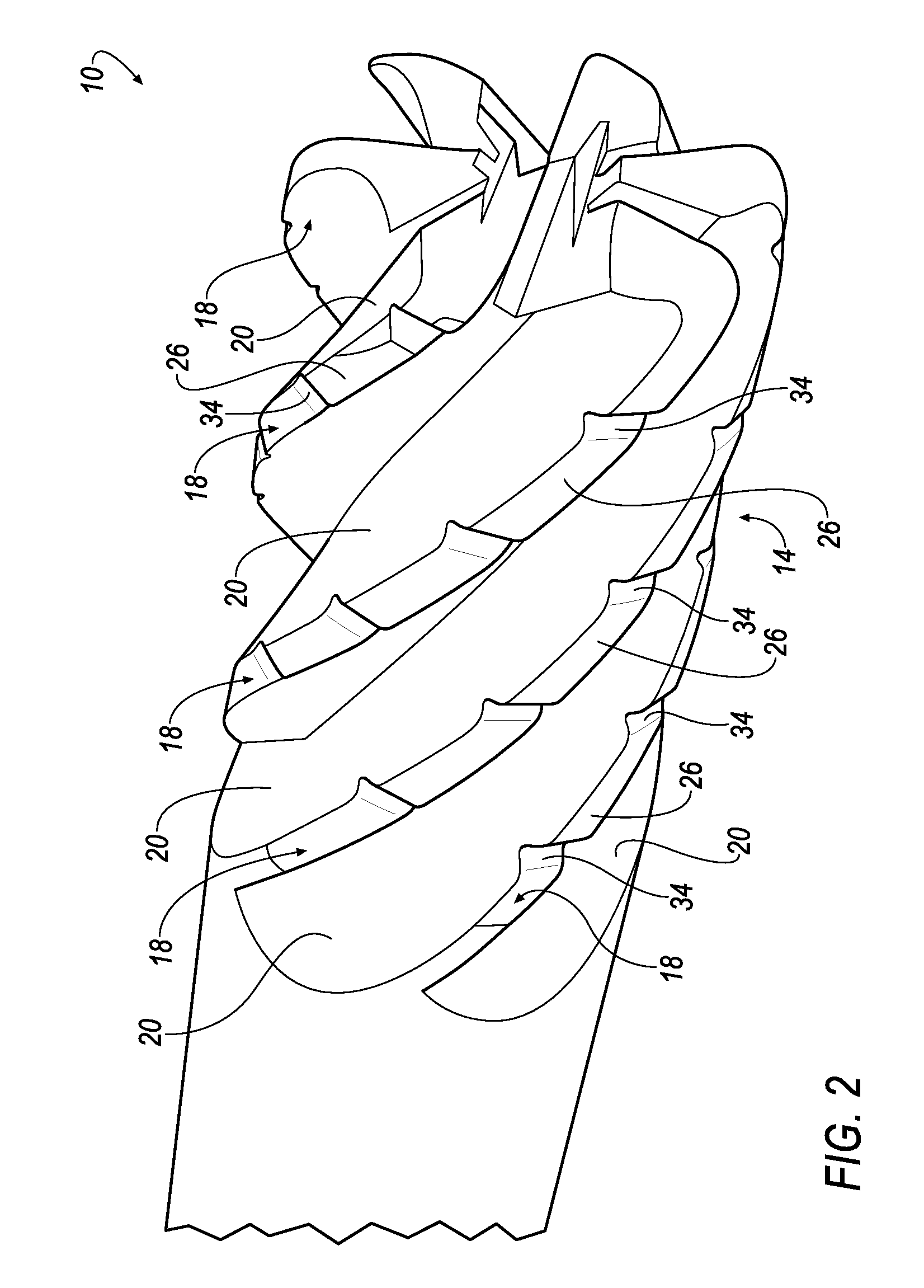
[0017]Referring now to FIGS. 1 and 2, a rotary cutting tool 10 is provided that includes a shank portion 12, a cutting portion 14 having a cutting tip 15, and a longitudinal axis 16. The overall shape of the cutting portion 14 may be, but is not limited to, a cylindrical shape or a frustoconical shape. The cutting portion 14 includes a plurality of blades 18 separated by flutes 20 extending the length of the cutting portion 14. In the illustrated embodiment, the rotary cutting tool 10 has a total of six (6) blades 18 and flutes 20. However, it will be appreciated that the invention is not limited by the number of blades and flutes, and that the invention can be practiced with a fewer or a greater number of blades and flutes. For example, the invention can be practiced with four (4) blades and flutes, eight (8) blades and flutes, and the like.

[0018]Referring now to FIGS. 3 and 4, each of the blades 18 has a leading face 22, a trailing face 24, and a land surface 26 bridging the leadi...


PUM

PropertyMeasurementUnit
Angleaaaaaaaaaa
Angleaaaaaaaaaa
Radiusaaaaaaaaaa

Abstract

A rotary cutting tool with a longitudinal axis includes a shank portion, a cutting portion, and a plurality of chip-breaking features. The cutting portion includes a plurality of blades and a plurality of flutes. The blades and flutes extend substantially along the length of the cutting portion and have unequally-indexed spacing. The flutes have a tapered depth along the longitudinal axis. Each blade includes a leading face, a trailing face, and a land surface that extends between the leading face and the trailing face. A plurality of chip-breaking features having a multi-radius profile are disposed in the land surfaces of the blades and are distributed in an offset chip breaker pattern among the blades such that each chip-breaking feature on one blade is not directly behind the chip-breaking features on immediately adjacent blades. The chip-breaking features on each blade are equidistant from each other.

Description

FIELD OF THE INVENTION[0001]The present invention pertains to a rotary cutting tool. More particularly, the present invention relates to an end mill having an offset chip breaker pattern such that each chip breaker on one blade is positioned between a respective chip breaker on the immediately adjacent blades.BACKGROUND OF THE INVENTION[0002]Rotary cutting tools, such as end mills, typically have a cylindrical configuration that includes a shank portion and a cutting portion. The cutting portion contains a plurality of helically disposed cutting blades that extend from a first end (i.e., the “shank end”) of the cutting portion adjacent the shank portion, toward the opposite end (i.e., the “free end”) of the cutting portion. In some embodiments, the cutting edges of the helical blades are disposed along a substantially constant radius with respect to the longitudinal axis of the tool. In other embodiments, generally referred to as “tapered” cutting tools, the cutting portion is subst...

Claims


Application Information

Patent Timeline
IPC IPC(8): B26D1/00
CPCB23C5/10B23C2210/086B23C2210/282B23C2210/405Y10T407/1966Y10T407/24Y10T407/1946Y10T407/1958B23C2210/48B23B27/22B23C5/12B23B51/00
Inventor DAVIS, DANNY RAY
Owner KENNAMETAL INC
Why Eureka
Try Eureka