Method and apparatus for bearer processing

Active Publication Date: 2010-08-26
HUAWEI TECH CO LTD
View PDF15 Cites 28 Cited by
  • Summary
  • Abstract
  • Description
  • Claims
  • Application Information

AI Technical Summary

Problems solved by technology

However, the UMTS and the SAE system have different procedures for bearer resource allocation, thus causing conflicts between the UMTS and the SAE system in the Bearer Resource Allocation procedures.

Method used


Image

  • Method and apparatus for bearer processing
  • Method and apparatus for bearer processing
  • Method and apparatus for bearer processing

Examples


first embodiment

[0059]FIG. 4 shows a flowchart of mapping the procedures of systems by notifying the SAE system of related information indicating reasons or types of bearer changes in the present invention.

[0060]S801. In the UMTS, the (secondary) PDP Context Activation procedure initiated by the UE and the PDP Context Modification procedure initiated by the UE, RAN, SGSN or S-GW (when the S-GW is the system border node and needs to play the role of the GGSN) may trigger a Request Bearer Resource Allocation message to the SAE system.

[0061]S802. In this embodiment, the border node (SGSN and / or S-GW) of these two systems may notify the SAE system of related information indicating reasons and / or types of bearer changes through different messages, a type indication parameter in the message or some fields in the parameter. In this embodiment, the SAE system is notified through a bearer ID carried in the Request Bearer Resource Allocation message of the SAE system.

[0062]S803. The PGW may use the obtained ...

second embodiment

[0065]the present invention describes a method for initiating a secondary PDP context activation by the UE, supposing the system border node is located in the SGSN. As shown in FIG. 5, the method includes the following steps:

[0066]S901: The UE sends an Activate Secondary PDP Context Request message to the SGSN to create a resource bearer. The request carries a network layer service access point ID—Netscape server application program interface (NSAPI) parameter wherein the parameter is correlated with the bearer ID / PDP context ID, a QoS parameter correlated with required bearer resources and a Correlation Transaction ID parameter correlated with an existing bearer / PDP context.

[0067]S902. The SGSN sends a Request Bearer Resource Allocation message carrying a bearer creation indication to the S-GW. The SGSN converts the Activate Secondary PDP Context Request message into a Request Bearer Resource Allocation message, and sends the request to the PGW through the S-GW, wherein the Request...

third embodiment

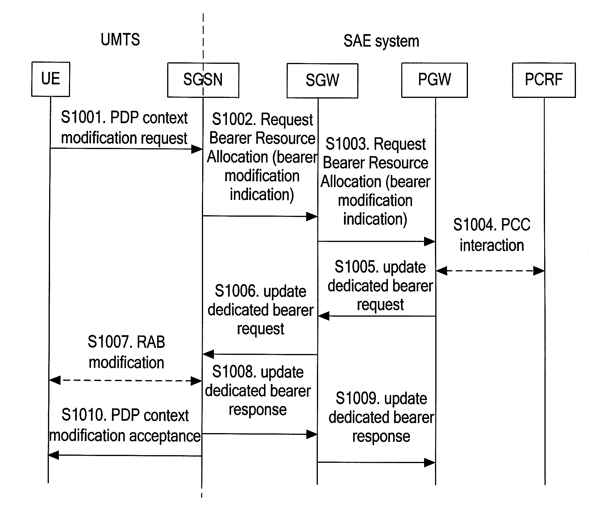
[0079]the present invention describes a method for initiating a PDP context modification by the UE, supposing the system border node is located in the SGSN. As shown inFIG. 6, the method includes the following steps:

[0080]S1001. The UE sends a PDP Context Modification Request to the SGSN to modify the resource bearer. The request may carry a QoS parameter correlated with the required bearer resources and a Procedure Transaction ID parameter correlated with the bearer / PDP context to be modified.

[0081]S1002. The SGSN sends a Request Bearer Resource Allocation message to notify the PGW of modifying the bearer, wherein the request may include a bearer modification indication. The SGSN converts the PDP Context Modification Request into a Request Bearer Resource Allocation message, and sends the Request Bearer Resource Allocation message to the PGW through the S-GW, wherein the Request Bearer Resource Allocation message carries a bearer ID, through the bearer ID the PGW can know that the ...


PUM


Abstract

A bearer processing method is disclosed. The method includes these steps: a system border node receives a Packet Data Protocol (PDP) Context Request initiated by a universal mobile telecommunication system (UMTS); the system border node adjusts a Request Bearer Resource Allocation message of a system architecture evolution (SAE) system or the PDP Context Request of the UMTS according to the received PDP Context Request to map the Bearer Resource Allocation procedure of the SAE system and the Bearer Resource Allocation procedure of the UMTS. The present invention can map the Bearer Resource Allocation procedure of the SAE system and the Bearer Resource Allocation procedure of the UMTS.

Description

CROSS-REFERENCE TO RELATED APPLICATIONS[0001]This application is a continuation of International Application No. PCT / CN 2008 / 072859, filed on Oct. 28, 2008, which claims priority to Chinese Patent Application No. 200710165462.9, filed on Oct. 29, 2007, both of which are hereby incorporated by reference in their entireties.FIELD OF THE INVENTION[0002]The present invention relates to a mobile communication technology, and in particular, to a method and apparatus for bearer processing.BACKGROUND OF THE INVENTION[0003]A universal mobile telecommunication system (UMTS) is a third generation mobile communication system that uses a wideband code division multiple access (WCDMA) air interface technology. The UMTS is usually called a WCDMA communication system. The UMTS includes a radio access network (RAN) and a core network (CN). The RAN is responsible for processing all radio access functions, while the CN is responsible for processing all voice calls and data connections in the UMTS, and...

Claims


Application Information

Patent Timeline
Patent Type & Authority Applications(United States)
IPC IPC(8): H04W72/00H04W76/12
CPCH04W72/0406H04W72/0453H04W72/04H04W92/02H04W76/022H04W76/12H04W72/20
Inventor ZHOU, JINYILIU, LANHU, HUADONG
Owner HUAWEI TECH CO LTD
Why Eureka
Try Eureka