Non-pneumatic tire

a technology of non-pneumatic tires and tires, applied in the direction of tires, high-resiliency wheels, vehicle components, etc., can solve the problem of inevitable structural problems such as blowouts, achieve satisfactory ride quality and handling qualities, prevent blowouts, and reduce weigh

Active Publication Date: 2010-09-02
BRIDGESTONE CORP
View PDF8 Cites 25 Cited by
  • Summary
  • Abstract
  • Description
  • Claims
  • Application Information

AI Technical Summary

Benefits of technology

[0035]According to the invention, it is possible to suppress an increase in weight, hardness, and rolling resistance to secure satisfactory ride qualities and handling qualities, and it is possible to prevent a blowout from occurring. In addition, it is possible to secure satisfactory handling qualities and durability, to make distribution of contact pressure uniform, and to prevent a blowout from occurring.

Problems solved by technology

In the known pneumatic tire filled with pressurized air when used, the possibility of a blowout is an inevitable structural problem.

Method used


Image

  • Non-pneumatic tire
  • Non-pneumatic tire
  • Non-pneumatic tire

Examples


first embodiment

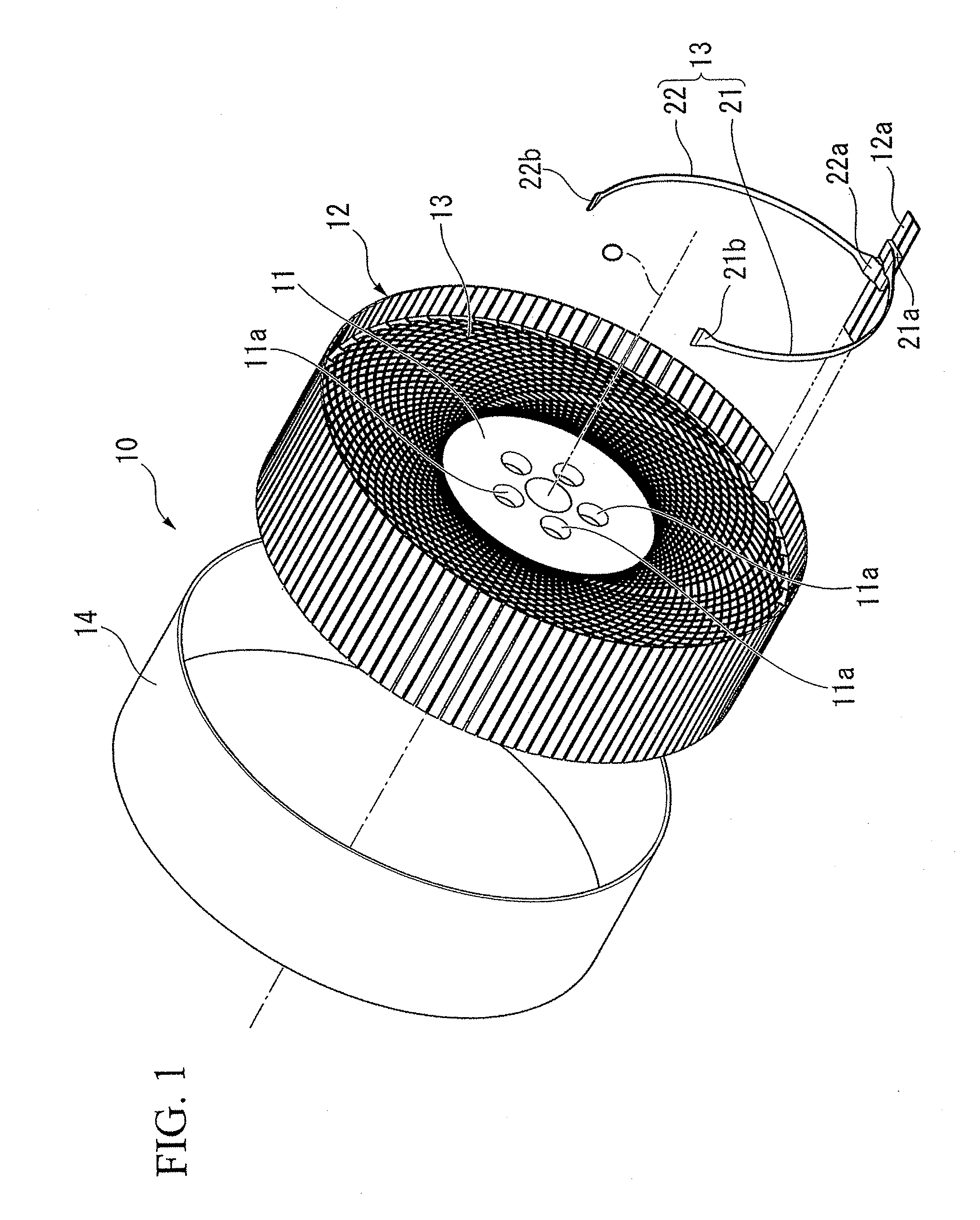
[0063]Hereinafter, a non-pneumatic tire according to the invention will be described with reference to FIG. 1 to FIG. 3.

[0064]The non-pneumatic tire 10 is provided with an installation disk 11 mounted on an axletree (not shown), a ring-shaped body 12 surrounding the installation disk 11 from the outside in the radial direction, a plurality of connection members 13 connecting an outer circumferential face of the installation disk 11 to an inner circumferential face of the ring-shaped body 12, and a tread rubber 14 provided over the entire outer circumferential face of the ring-shaped body 12.

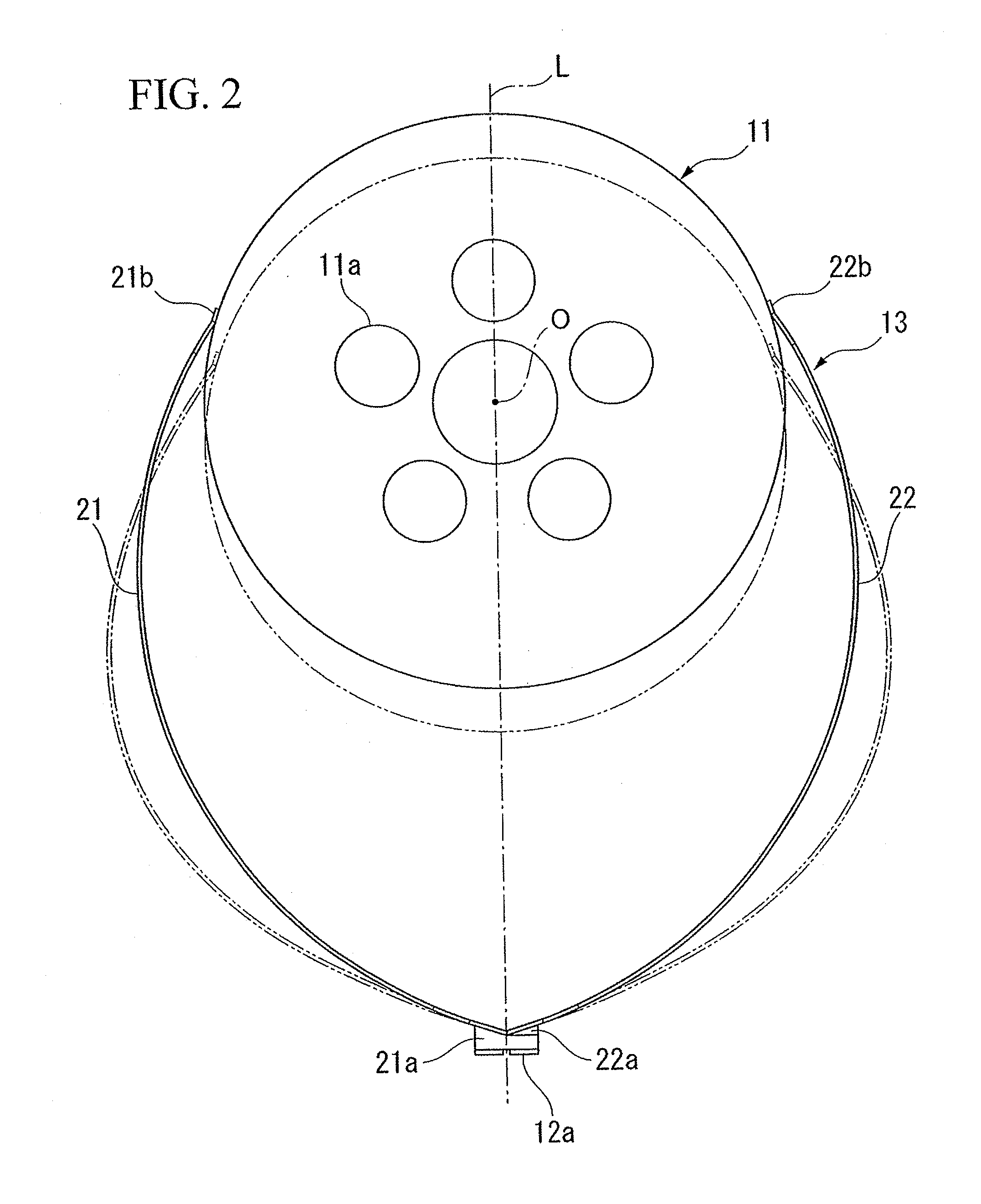
[0065]The installation disk 11 has a circular shape in a side view of the non-pneumatic tire 10 from a direction of an axial line O, and a plurality of installation holes 11a are formed at the radial center. For example, bolts are inserted into such installation holes 11a, and are coupled to female screw portions formed in the axletree by screws, thereby mounting the installation disk 11 on the a...

second embodiment

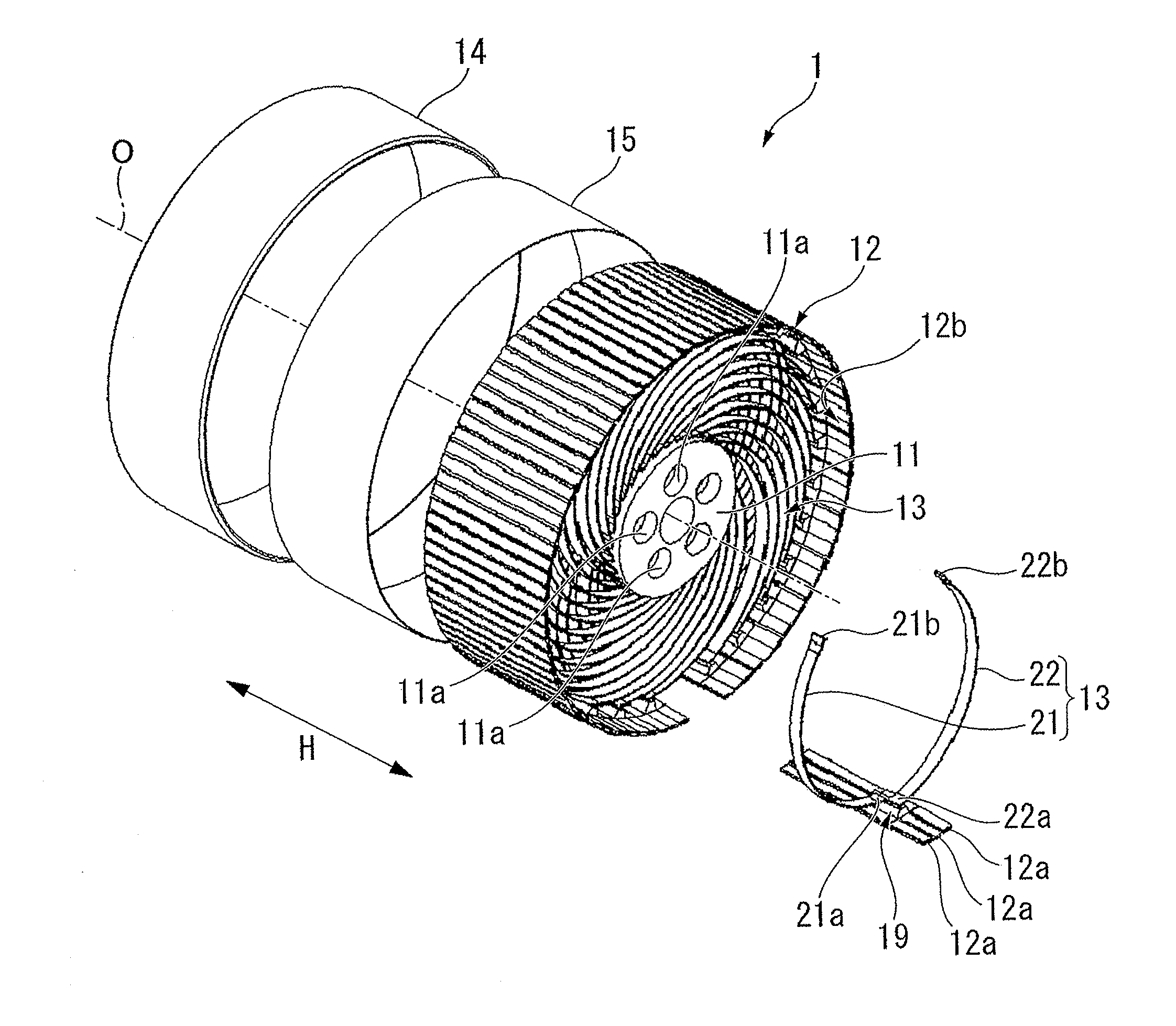
[0108]Hereinafter, a non-pneumatic tire according to the invention will be described with reference to FIG. 5 to FIG. 7B.

[0109]The non-pneumatic tire 1 is provided with an installation disk 11 mounted on an axletree (not shown), a ring-shaped body 12 surrounding the installation disk 11 from the outside in the tire-radial direction, a plurality of connection members 13 connecting an outer circumferential face of the installation disk 11 to an inner circumferential face 12b of the ring-shaped body 12, a tread rubber 14 provided over the entire outer circumferential face of the ring-shaped body 12, and a reinforcement layer 15 provided between the ring-shaped body 12 and the tread rubber 14.

[0110]The installation disk 11 has a circular shape in a side view of the non-pneumatic tire 1 from a direction of an axial line O, and a plurality of installation holes 11a are formed at a radial center portion. For example, bolts are inserted into such installation holes 11a, and coupled to femal...

third embodiment

[0142]As described above, according to the non-pneumatic tire 2 of the third embodiment, the first end 21a and the second end 21b of the first connection plate 21 and the first end 22a and the second end 22b of the second connection plate 22 (hereinafter, referred to as connection parts) are rotatably supported around the rotation axial line R. Therefore, when the installation disk 31 and the ring-shaped body 12 are relatively changed in position in the tire-radial direction, the tire-circumferential direction, or the tire-widthwise direction H by external force applied to the non-pneumatic tire 2, it is possible to prevent the connection parts from being partially and greatly deformed, by rotating the connection parts of the first and the second connection plates 21 and 22 around the rotation axial line R. Accordingly, the first and the second connection plates 21 and 22 are uniformly deformed overall with little bias, and it is possible to ease the load applied to the connection p...


PUM


Abstract

A plurality of connection members 13 connecting an installation disk 11 to a ring-shaped body 12 are formed, in a side view of the non-pneumatic tire, to be axisymmetrical about an imaginary line connecting the respective first ends 21a and 22a of first connection plates 21 and second connection plates 22 to an axial line O and extending in a tire-radial direction. The connection members 13 are arranged in a tire-circumferential direction such that the first connection plates 21 are arranged at a first tire-widthwise position in the tire-circumferential direction and that the second connection plates 22 are arranged at a second tire-widthwise position in the tire-circumferential direction. According to the invention, it is possible to suppress an increase in the weight, hardness, and rolling resistance to secure satisfactory ride qualities and handling qualities, and it is possible to prevent a blowout from occurring.

Description

TECHNICAL FIELD[0001]The present invention relates to a non-pneumatic tire which need not be filled therein with pressurized air when used.[0002]Priority is claimed on Japanese Patent Application No. 2007-230238, filed Sep. 5, 2007, and Japanese Patent Application No. 2008-053917, filed Mar. 4, 2008, the content of which is incorporated herein by reference.BACKGROUND ART[0003]In the known pneumatic tire filled with pressurized air when used, the possibility of a blowout is an inevitable structural problem.[0004]As a non-pneumatic tire capable of preventing a blowout from occurring, there is a so-called solid tire having a solid structure, which is filled therein with rubber, as described in Patent Document 1.[0005][Patent Document 1] Japanese Patent Application, First Publication No. H06-293203DISCLOSURE OF THE INVENTIONProblem to be Solved by the Invention[0006]The known non-pneumatic tire is heavy in weight and has great hardness and rolling resistance as compared with the pneumat...

Claims


Application Information

Patent Timeline
Patent Type & Authority Applications(United States)
IPC IPC(8): B60B9/02
CPCB60B9/26B60C7/22B60C7/18
Inventor ABE, AKIHIKO
Owner BRIDGESTONE CORP
Why Eureka
Try Eureka