Magnetic rail bond

a technology of magnetic rail and bonding rod, which is applied in the direction of rail devices, connection of coupling devices, ways, etc., can solve the problems of low reliability, and more likely to fail or break the rail

Inactive Publication Date: 2010-09-02
WILLIAMS MARK A
View PDF15 Cites 20 Cited by
  • Summary
  • Abstract
  • Description
  • Claims
  • Application Information

AI Technical Summary

Benefits of technology

[0005]An illustrative embodiment of the present invention is directed to a method of forming an electrical connection between an electrical conductor and a railway rail. Pursuant to said method, an electrically-conductive magnet assembly coupled to an end of an electrical conductor is provided. The electrically-conductive magnet assembly is coupled to a railway rail via magnetic force. The magnetic coupling

Problems solved by technology

This drilling or pounding can cause a flaw in the rail, making the rail more likely to fail or break.
The heating of the rail that is inherent in the welding proces

Method used


Image

  • Magnetic rail bond
  • Magnetic rail bond
  • Magnetic rail bond

Examples


Embodiment Construction

[0016]Illustrative embodiments of the invention will be described with respect to the drawings. The drawings and the associated descriptive text show and describe, by way of illustration, specific implementations of the present invention. Other examples of implementations may be utilized and structural changes can be made without departing from the scope of the invention.

[0017]In general, the present invention comprises rail a bond apparatus utilizing a magnetic coupling of an electrical conductor to a railroad rail and methods of magnetically coupling an electrical conductor to a railroad rail.

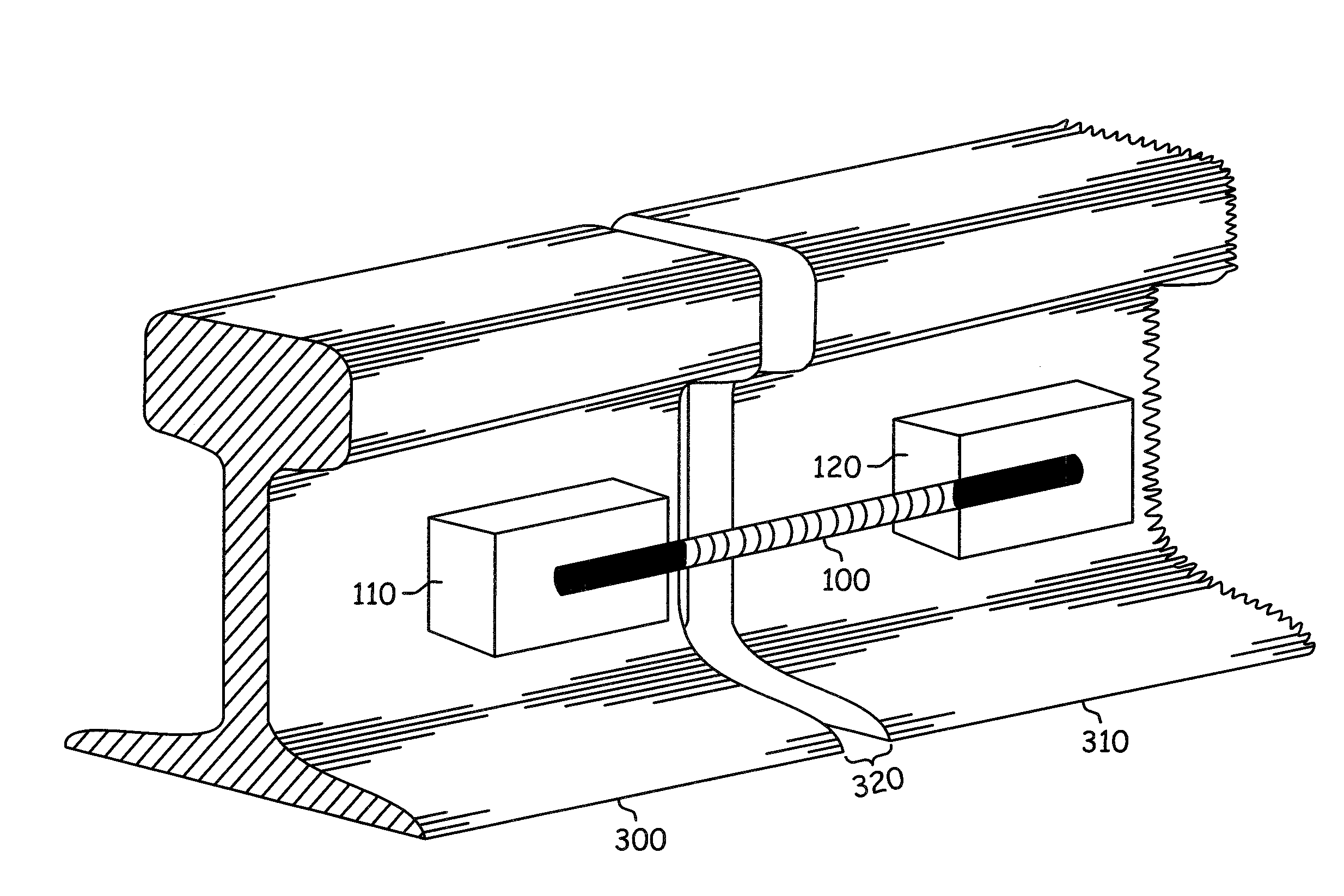
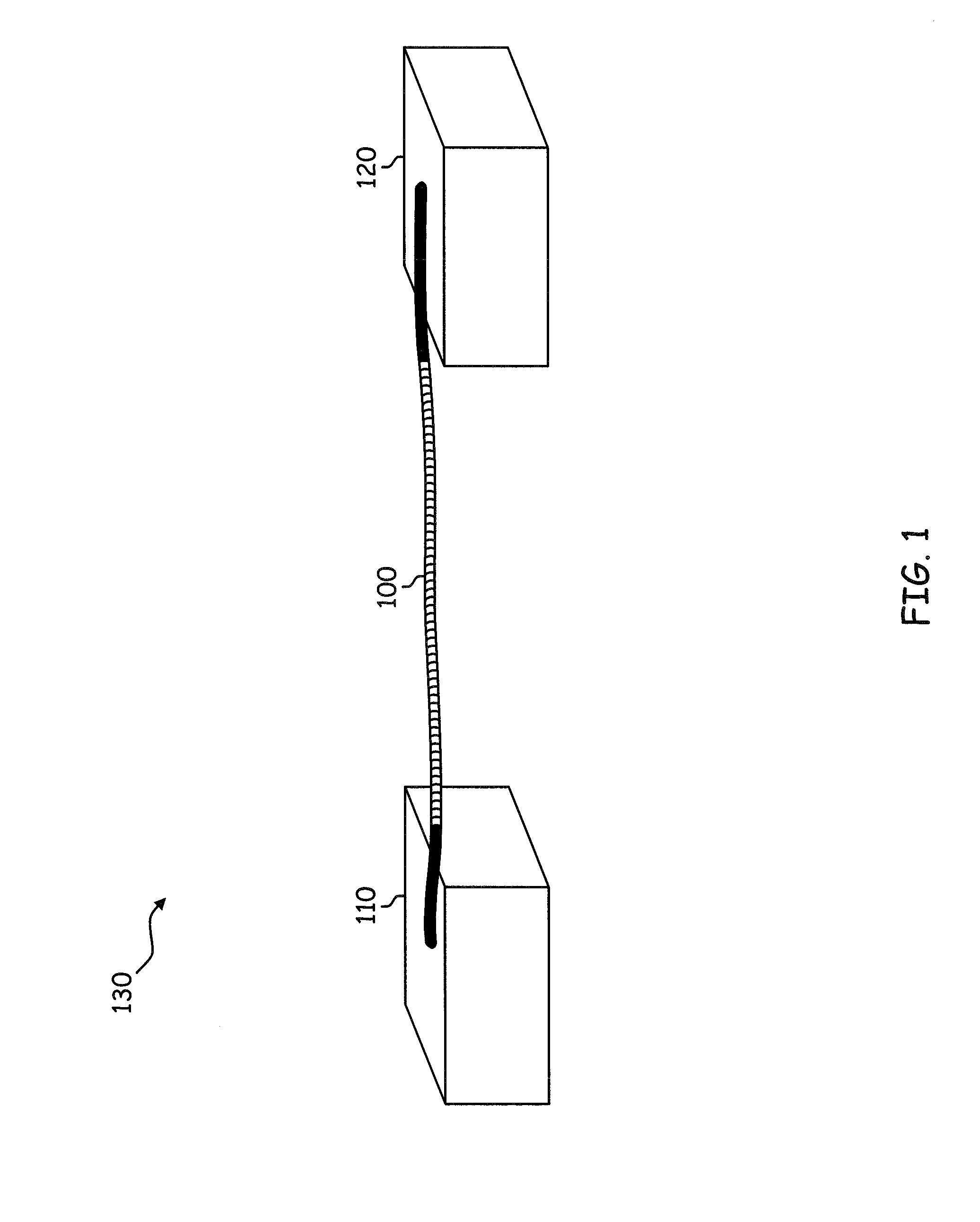
[0018]FIG. 1 shows a magnetic rail bond 130 according to an illustrative embodiment of the present invention. The rail bond 130 of FIG. 1 includes an electrically conductive cable 100 and two magnets 110, 120 mechanically and electrically coupled to the cable at both ends of the cable 100. In an illustrative embodiment of the invention, the magnets 110, 120 are comprised of a magnetic materia...


PUM


Abstract

Magnetic means and apparatus for implementing rail bonds and rail feeds. A rail bond embodiment comprises an electrical conductor. Mechanically and electrically coupled to each end of the electrical conductor is a magnet that comprises a magnetic material that is plated with an electrically conductive material. In an alternative embodiment, the magnet comprises a magnetic material that is disposed between two pieces of steel or other metal. In operation, the two magnets are attached to two rail sections, across a joint separating the rails, via the attractive magnetic force between each magnet and its associated rail. In this way, the electrical circuit comprising the rails is maintained.

Description

CROSS-REFERENCE TO RELATED APPLICATIONS[0001]This application claims priority to U.S. Provisional Patent Application 61 / 156,189, filed on Feb. 27, 2009, the contents of which are hereby expressly incorporated herein by reference.BACKGROUND OF THE INVENTION[0002]The rails of a railroad track are sometimes used as electrical conductors that carry electrical signals. For example, track circuits are used to detect the presence or absence of a train on rail tracks. This information can then be used to inform signalers and control relevant signals. In a typical track circuit, power is applied to each rail at one end of a section of track, such as a block. An electrical relay is electrically coupled across the rails at an opposite end of the section of track. When no train is present, the relay is energized by the current flowing through the rails. When a train is present, its wheels and axle electrically short the circuit formed by the rails. This causes the current to the relay to drop, ...

Claims


Application Information

Patent Timeline
IPC IPC(8): B60M5/00
CPCH01R13/6205B60M5/00
Inventor WILLIAMS, MARK A.
Owner WILLIAMS MARK A
Why Eureka
Try Eureka