
Cutter and printer with cutter

Inactive Publication Date: 2010-09-02
SEIKO EPSON CORP
View PDF17 Cites 7 Cited by
  • Summary
  • Abstract
  • Description
  • Claims
  • Application Information

AI Technical Summary

Benefits of technology

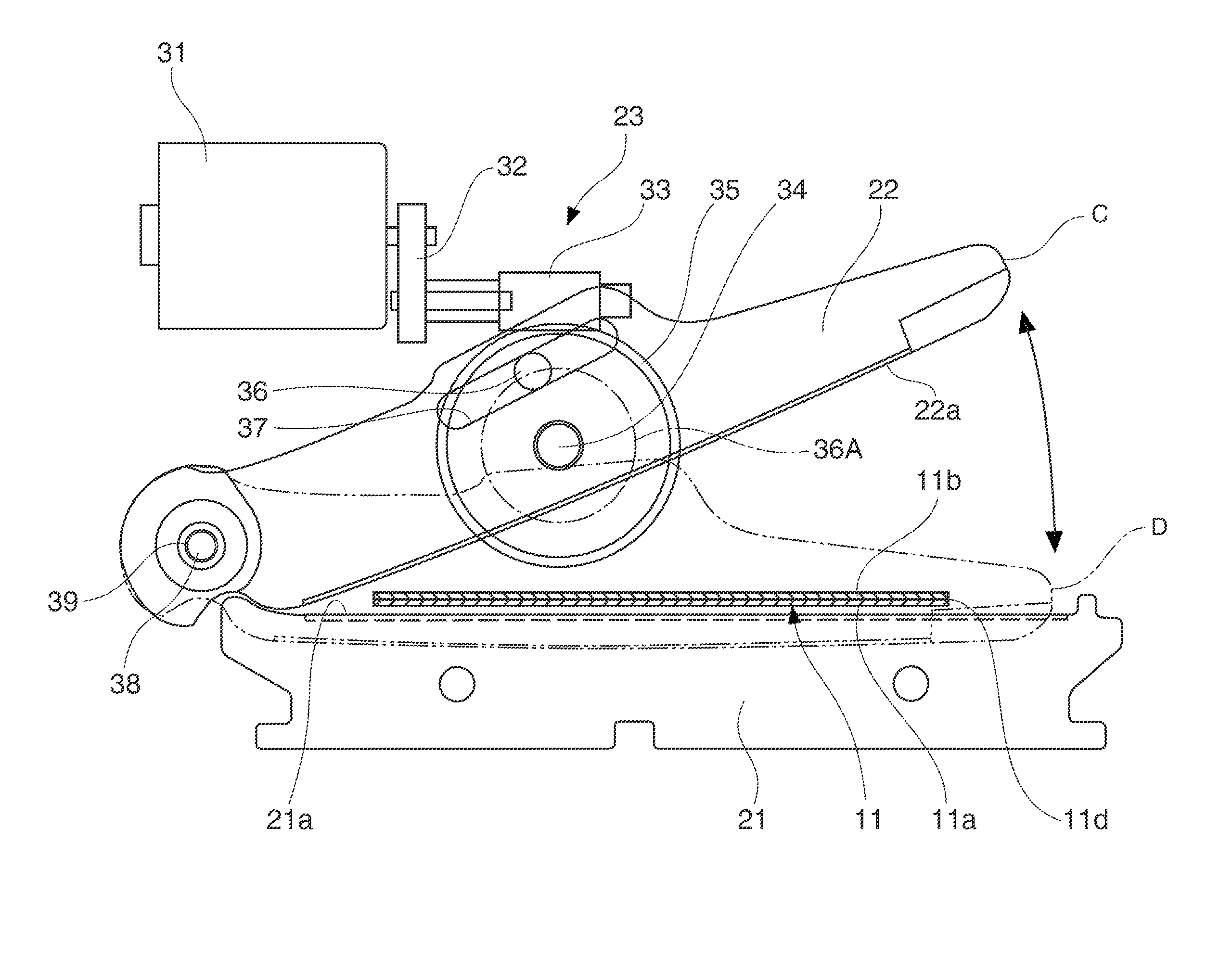
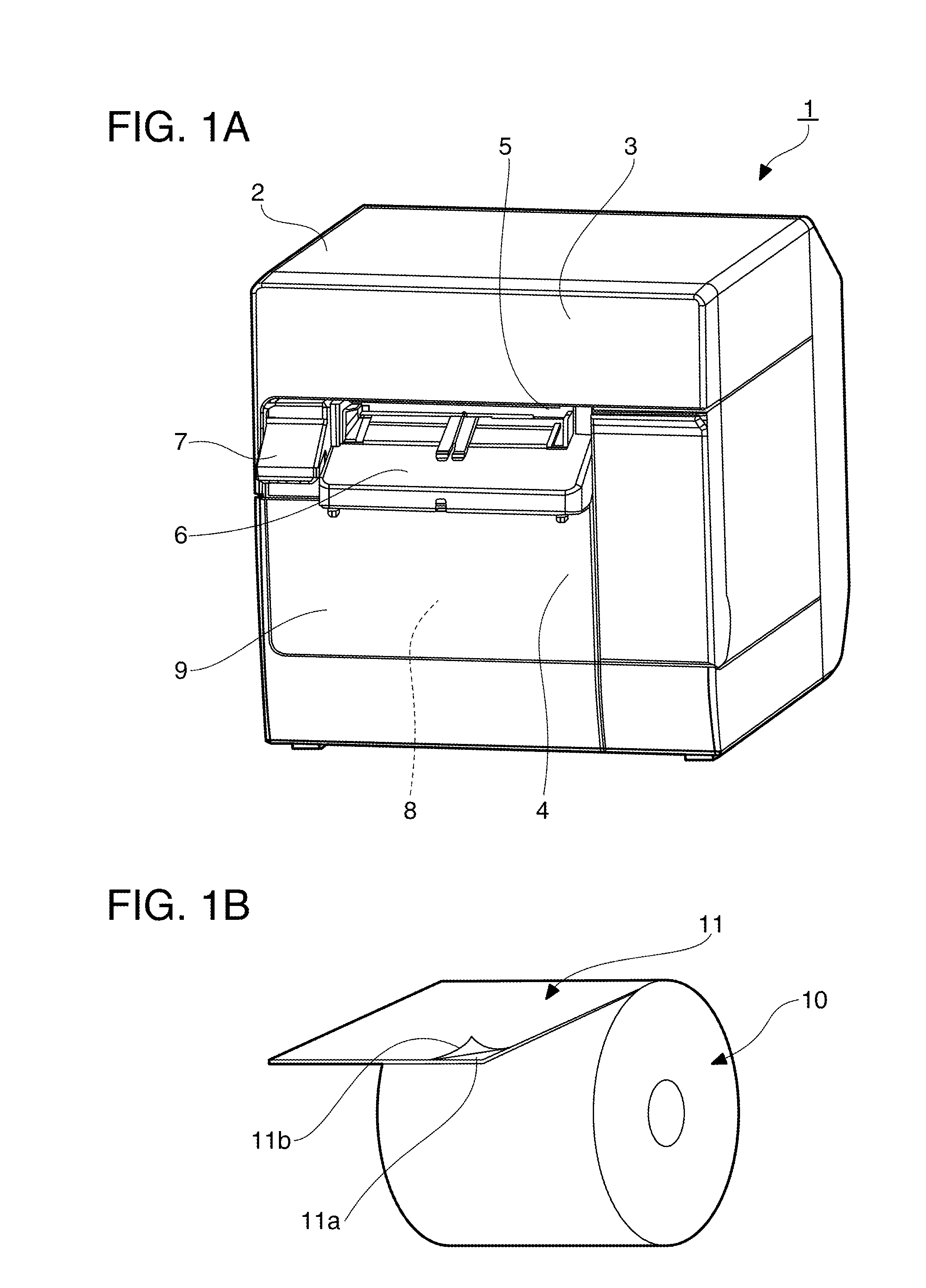
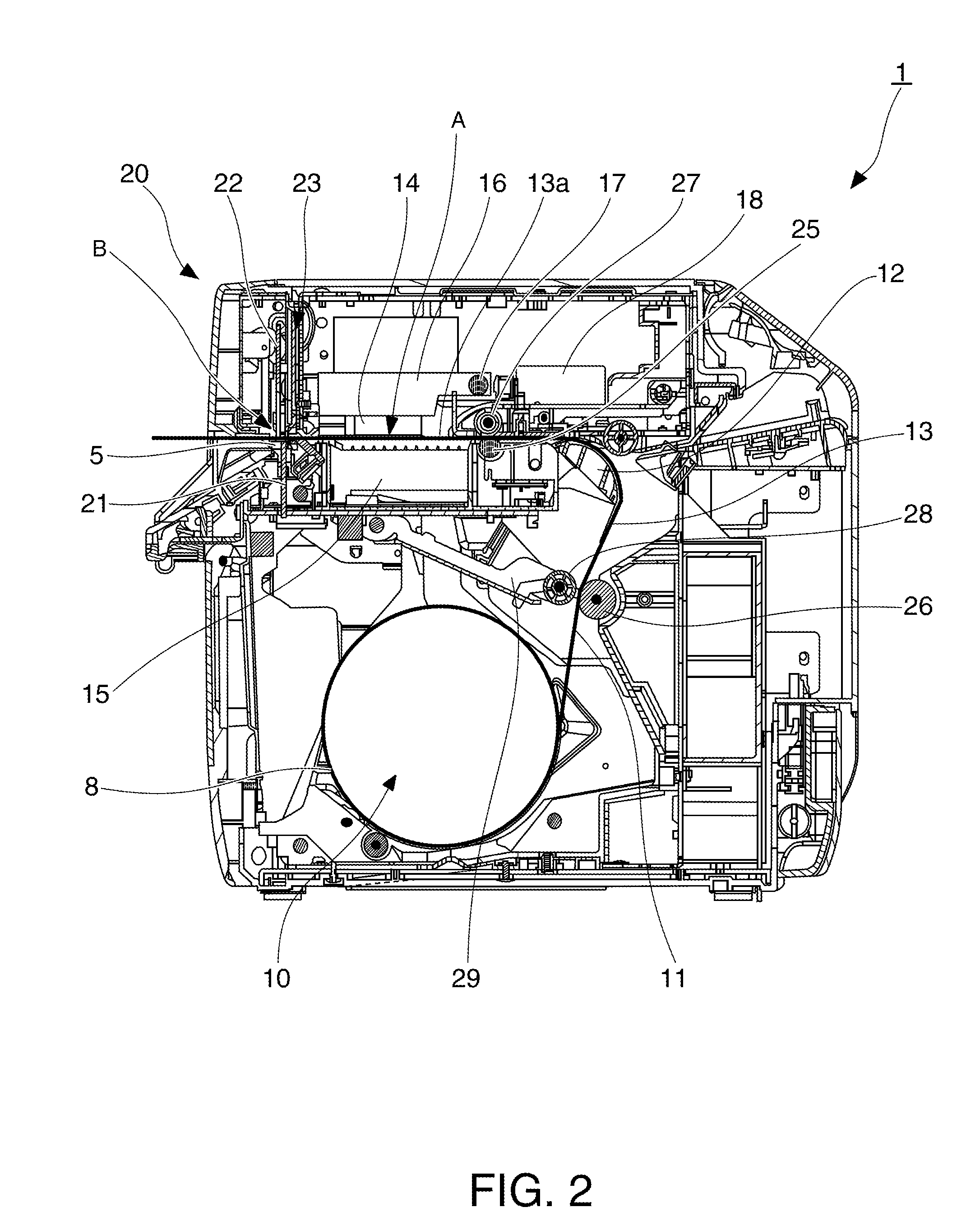
[0010]A cutter (an automatic cutter) and a printer having a cutter (an automatic cutter) are provided. Such a cutter may enable the discharging of a cut-off portion of a recording medium (e.g., roll paper, label paper) in a stable condition from a narrow paper exit of a printer. Such a cutter can also be used to cut suitable sheet materials (e.g., sheet metal, sheet plastic, etc.).
[0051]With the disclosed paper cutters, however, the surface of the paper exit on the fixed knife side is formed outside the range of movable knife movement when the movable knife cuts. Therefore, because the movable knife does not push the upstream end part of the cut-off portion beyond the edge of the exit when the knife moves, the upstream end part of the cut-off portion is always inside the edge of the paper exit, and paper jams and curling may be inhibited or prevented. The ease of use of the device is therefore good because the occurrence of problems such as paper jams are reduced or eliminated, and the cut-off portion may be prevented from spring out of the paper exit and scattering when the movable knife returns to the standby position.

Problems solved by technology

This may result in a paper jam.
If the cut-off 103 pops out of the paper exit 100 and falls onto the floor, for example, there is a significant loss of user convenience.
In addition, a problem with the related art is that when cutting paper the cutting edge of the movable knife moves beyond the edge of the paper exit thereby causing the upstream end part of the cut-off portion to curl.
In addition, a problem with the related art is that when cutting paper, the cutting edge of the movable knife moves outside the edge of the paper exit, the movable knife pinches the upstream end of the cut-off portion, and paper jams may result.

Method used


Image

  • Cutter and printer with cutter
  • Cutter and printer with cutter
  • Cutter and printer with cutter

Examples


Embodiment Construction

of the Invention

[0049]With the cutter and printer having a cutter according to at least of one embodiment of the invention, the paper exit is defined by mutually opposing surfaces, and the size of the opening between these opposing surfaces can be limited to a short distance of an opening from outside the range of movable knife movement to substantially the same position as the cutting edge of the fixed knife. Insertion of foreign objects from outside the paper exit may therefore be reduced or prevented.

[0050]In addition, a problem with the related art is that when cutting paper the cutting edge of the movable knife moves beyond the edge of the paper exit thereby pushing the upstream end part of the cut-off portion beyond the edge of the paper exit, which may cause a paper jam. And pushing the upstream end part beyond the edge of the paper exit may cause the upstream end part of the cut-off portion to curl, resulting in the curled part of the cut-off portion springing back when the ...


PUM

PropertyMeasurementUnit
Lengthaaaaaaaaaa
Adhesivityaaaaaaaaaa

Abstract

A printer with a cutter is provided that can discharge cut-offs in a stable condition. A printer includes a transportation path, a transportation mechanism that conveys a recording medium along the transportation path, a fixed knife having a cutting edge, a movable knife having a cutting edge and moving between a standby position and a cutting-completed position, and an exit disposed along the transportation path. The exit includes a narrow opening defined by a first elongated side offset from the transportation path beyond the movable-knife cutting edge in the cutting-completed position, and a second elongated side opposite the first elongated side and offset from the transportation path opposite to the first elongated side. The second elongated side can be located immediately adjacent to the transportation path, for example, by less than or equal to 2 mm.

Description

CROSS-REFERENCES TO RELATED APPLICATIONS[0001]This application claims priority under 35 U.S.C. §119 to Japanese Patent Application No. 2009-047661 filed on Mar. 2, 2009, the entire disclosure of which is expressly incorporated by reference herein.BACKGROUND[0002]1. Technical Field[0003]The present invention relates to an automatic cutter (a cutter) that cuts recording paper or other continuous paper web disposed between a movable knife and a fixed knife by causing the movable knife to move toward the fixed knife and to slide along the fixed knife to cut the medium therebetween, and relates to a printer having the automatic cutter. More particularly, the invention relates to an automatic cutter and to a printer having the automatic cutter that can discharge the cut-off portion (the paper that was cut off) in a stable condition from the paper exit.[0004]2. Related Art[0005]Printers that print on recording paper such as roll paper or label paper may have an automatic cutter for cutting...

Claims


Application Information

Patent Timeline
IPC IPC(8): B41J11/66B26D7/00B26D1/30
CPCB26D1/085B41J11/70B26D7/32B26D1/305Y10T83/9447Y10T83/2218Y10T83/2196
Inventor SHIROTORI, MOTOYOSHITOMOMATSU, SHINSUKE
Owner SEIKO EPSON CORP
Learn More