Orthodontic device

Inactive Publication Date: 2010-09-09
HAMEIRI YOAV
View PDF8 Cites 4 Cited by
  • Summary
  • Abstract
  • Description
  • Claims
  • Application Information

AI Technical Summary

Benefits of technology

[0034]Preferably, the slot comprises a flap for preventing the band from sliding out of said slot in the direction from which it was inserted. Preferably, the flap is repositionable to allow the band to slide out of the slot in the direction from which it was inserted.
[0035]Preferably, the inner surface of the band comprises a rough texture for increasing retention around the tooth.

Problems solved by technology

Additionally, during the bracket mounting process, the force applied when pulling the archwire to connect the brackets often results in the brackets being pulled off the teeth.
Moreover, in cases of especially severe malocclusions and deep bites, blocking devices must be placed in the mouth to prevent the jaws from performing a complete bite, which would potentially cause the brackets to break off from the teeth.
It is particularly difficult to attain dryness during this procedure when attaching brackets to the lingual surfaces, and especially to the molar and premolar teeth due to the accumulation of saliva at the back of the mouth.
The process of determining the appropriate band considerably lengthens the time it takes to complete the braces fitting procedure.
Each band is placed by utilizing a dental tool known as a “pusher”, which often slips off the band and cuts the gingiva, causing bleeding to occur.
This can allow food particles and debris to become lodged at the base of the tooth, underneath the gingiva, and can lead to inflammation of the gingival tissue, and eventually to other dental problems.
When bands are required to be positioned around a tooth that is covered by a temporary or permanent crown, the pressure applied when fitting the band around the tooth often causes the crown to become dislocated, and fall off the tooth.
This period is typically uncomfortable for the patient and requires an additional visit to the orthodontist to place the separators in the mouth.
However, all of these devices are associated with difficulties and problems of their own.

Method used


Image

  • Orthodontic device
  • Orthodontic device
  • Orthodontic device

Examples


Embodiment Construction

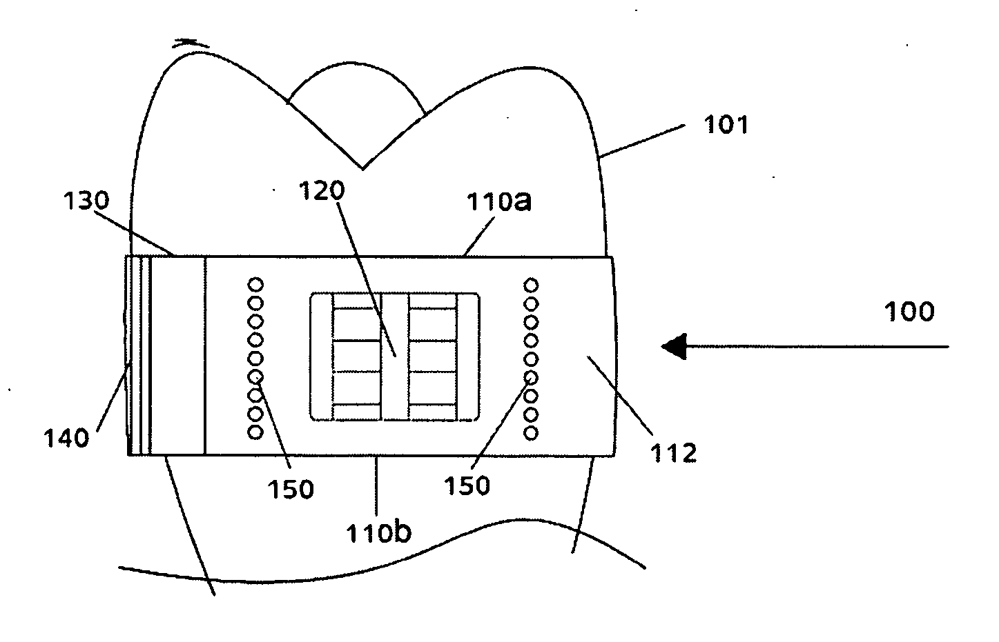
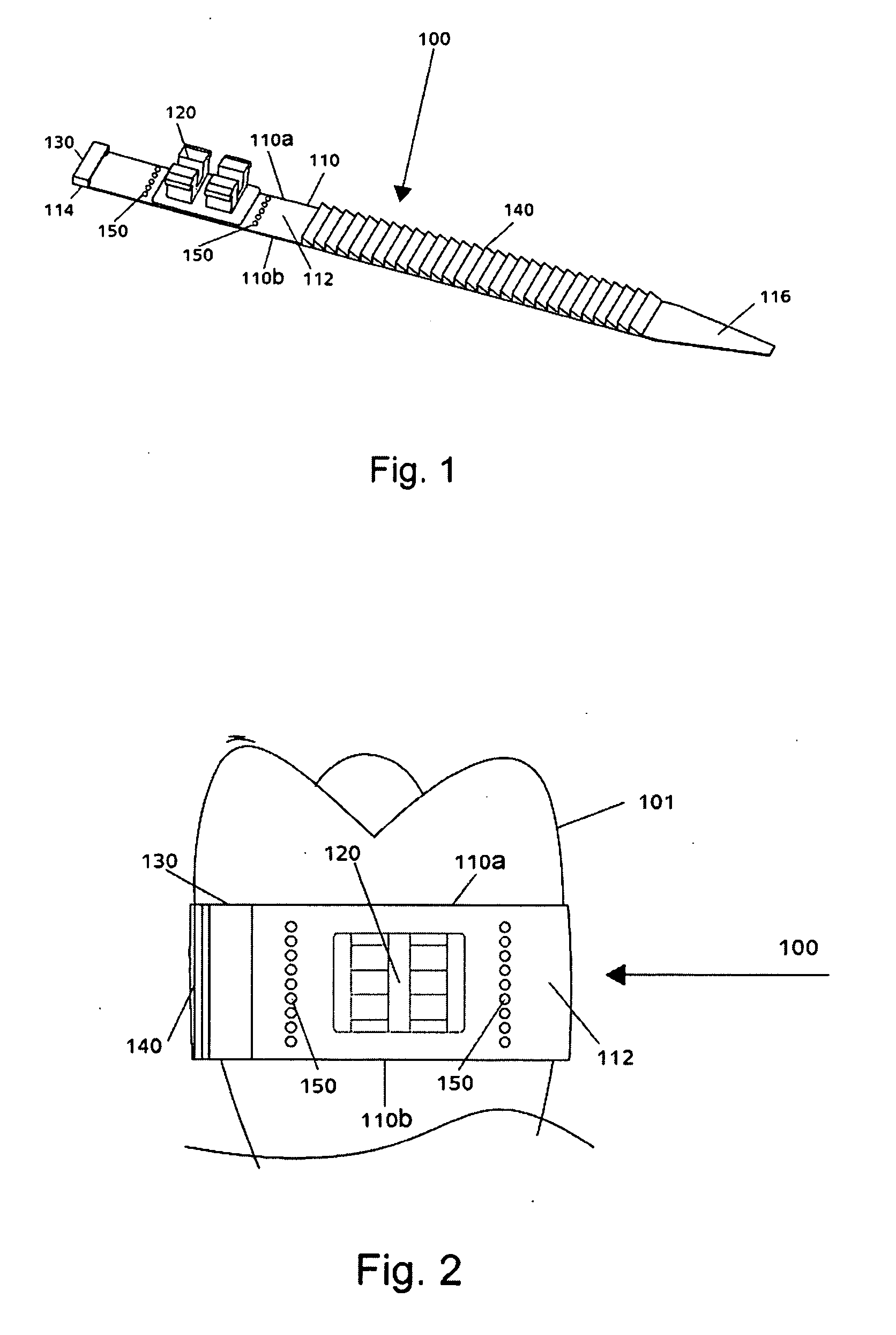
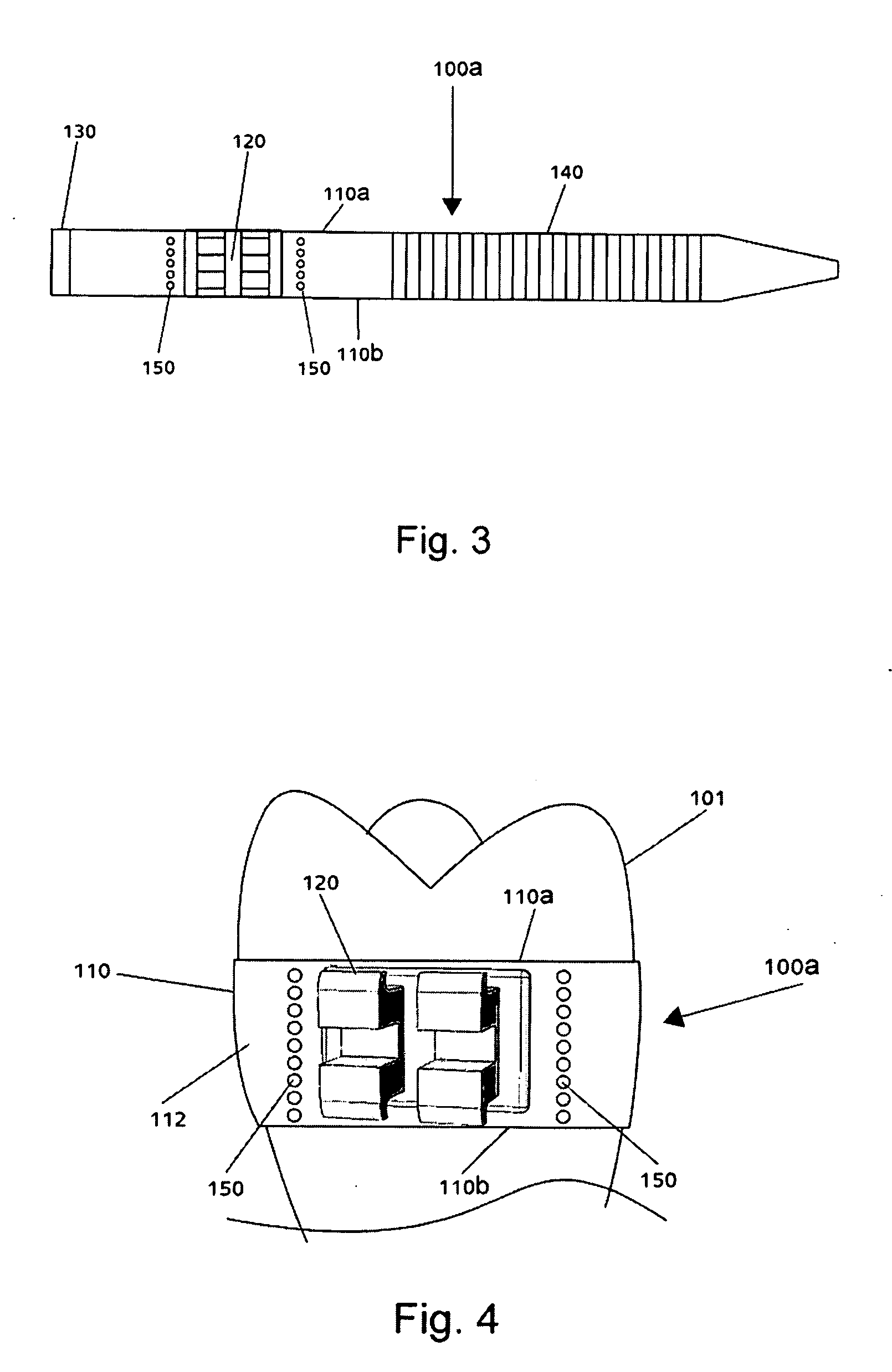
[0050]The procedure of placing braces within the mouth is associated with various difficulties, both for the patient as well as the orthodontic practitioner. The length of time that the procedure takes, as well as the bleeding that is often caused, is uncomfortable and painful to the patient. For the orthodontist, dependency on a stock of correctly sized bracket bands and trial and error, leads to a lengthy procedure time, and reduces the number of patients he can see per day. In light of these, among other problems, the present invention provides an orthodontic device that increases the time efficiency as well as reduces the discomfort involved with the procedure. The device is a flexible band having a wire holding mechanism attached thereto, which is positioned around a desired tooth, and which allows for adjusting to a suitable diameter in order to fit around the tooth.

[0051]A preferred embodiment of the orthodontic device of the present invention is shown in FIG. 1 in a perspect...


PUM


Abstract

An orthodontic device comprising an elongated flexible band for wrapping around a tooth. The band comprises an inner surface for contacting the tooth and an outer surface having a wire holding mechanism affixed thereto. The device further comprises a locking mechanism comprising a slot located at a first end of the band and a series of stopper elements protruding from the outer surface of the band. A second end of the band and at least a portion of the stopper elements are insertable through the slot for tightening the band around the tooth. The band further comprises a marking for indicating a preferred location for separating the portions of the band comprising the locking mechanism components from the portion of the band comprising the wire holding mechanism. Each marking is situated on one of each sides of the wire holding mechanism.

Description

FIELD OF INVENTION [0001]The present invention relates to the field of dentistry. In particular, the present invention relates to orthodontics. More particularly, the present invention relates to a device for improving the procedure of applying braces to teeth.BACKGROUND OF INVENTION [0002]Orthodontic braces (or simply, braces) are used to correct misalignments of teeth. Typically, brackets are affixed to the buccal side of at least some of the teeth of one or both of the upper arch (maxilla) and the lower arch (mandible). One or more wires (archwires) join the brackets and apply a pulling force to the misaligned teeth to correct the irregularities in their positions. Due to the unaesthetic appearance of the brackets and wire which are seen protruding from the teeth every time the mouth is opened, in some cases, the brackets are affixed to the lingual side of the teeth to keep the braces hidden from the outside view.[0003]In order to affix a bracket to a tooth, a portion of the toot...

Claims


Application Information

Patent Timeline
IPC IPC(8): A61C7/00
CPCA61C7/18
Inventor HAMEIRI, YOAV
Owner HAMEIRI YOAV
Why Eureka
Try Eureka