Electrical connector having detachable cover

a technology of electric connectors and covers, applied in the direction of coupling devices, two-part coupling devices, coupling devices with four or more poles, etc., can solve the problem of risking the termination between cables and terminals, and achieve the effect of improving configuration

Inactive Publication Date: 2010-09-09
HON HAI PRECISION IND CO LTD
View PDF4 Cites 12 Cited by
  • Summary
  • Abstract
  • Description
  • Claims
  • Application Information

AI Technical Summary

Benefits of technology

[0005]Accordingly, an object of the present invention is to provide an electrical connector with an improved configuration which can provide a preferred engagement therein.
[0006]In order to achieve the object set forth, an electrical connector includes an insulative housing having a main body and a supporting board extending downward from the main body so as to form an L-shaped configuration. The main body defines a plurality of receiving passageways extending along a front-to-rear direction and then runs through the supporting board along a vertical direction. A pair of guiding grooves are respectively formed at opposite inner sides of the main body. A plurality of terminals are retained in the receiving passageways. A cover defines locking portions at opposite sides thereof for movably received in the guiding grooves and covers the terminals for preventing outward movement of the terminals.

Problems solved by technology

However, as there is no retention between the cover and the insulative housing in a vertical direction, the cover may get loosed from the insulative housing during the usage of the connector, risking the termination between the cables and the terminals.

Method used


Image

  • Electrical connector having detachable cover
  • Electrical connector having detachable cover
  • Electrical connector having detachable cover

Examples


Embodiment Construction

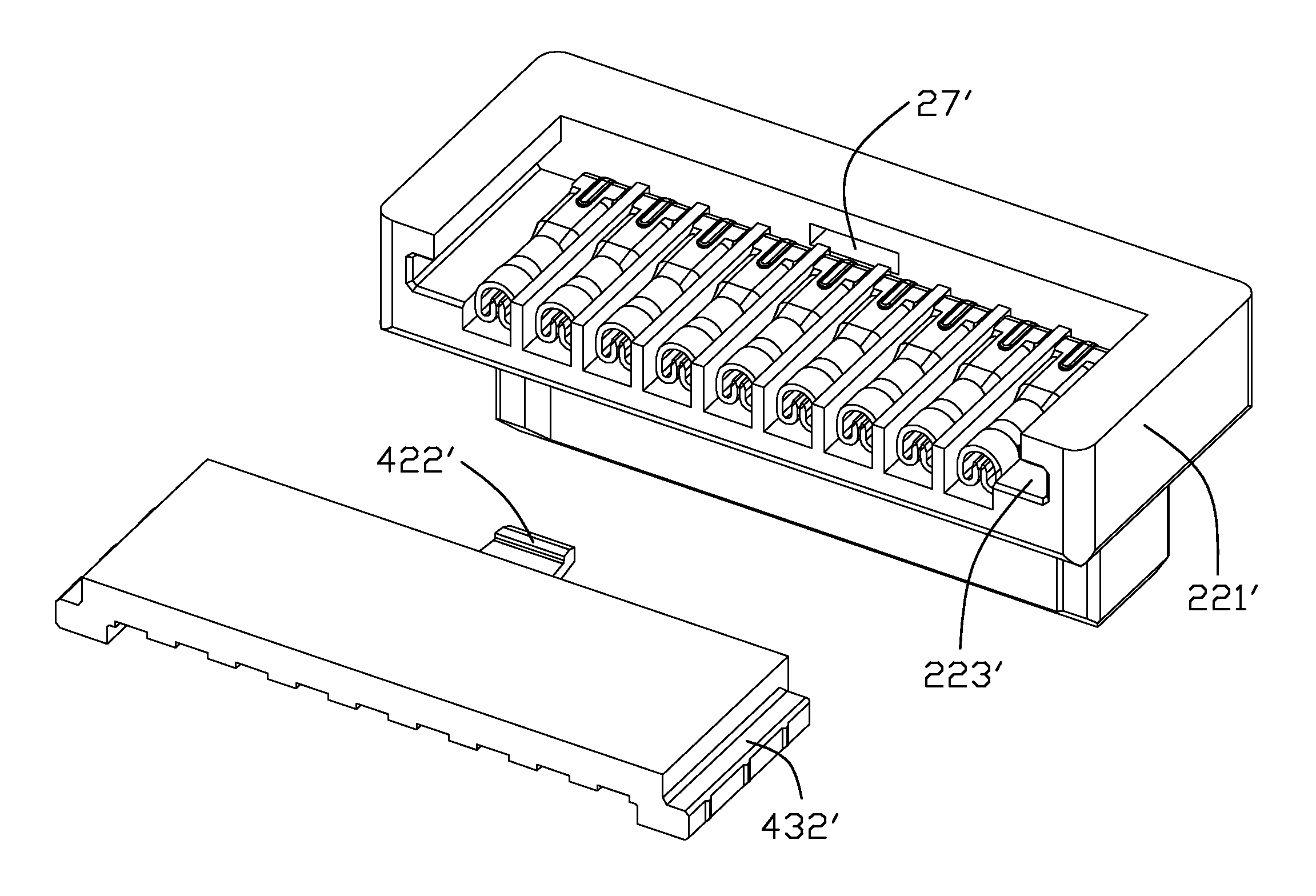
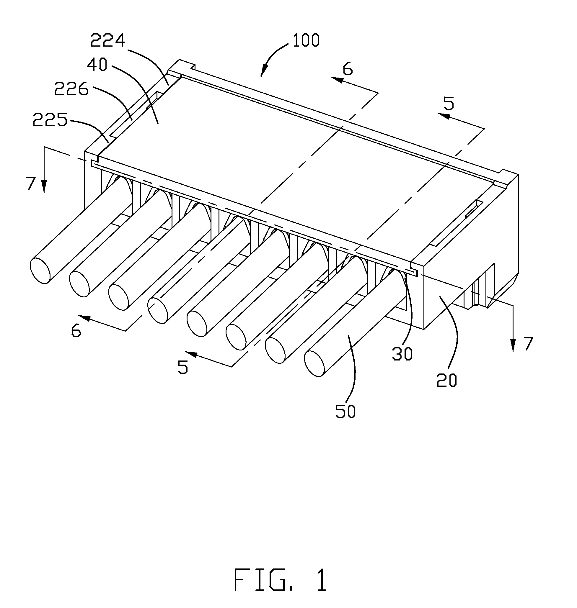
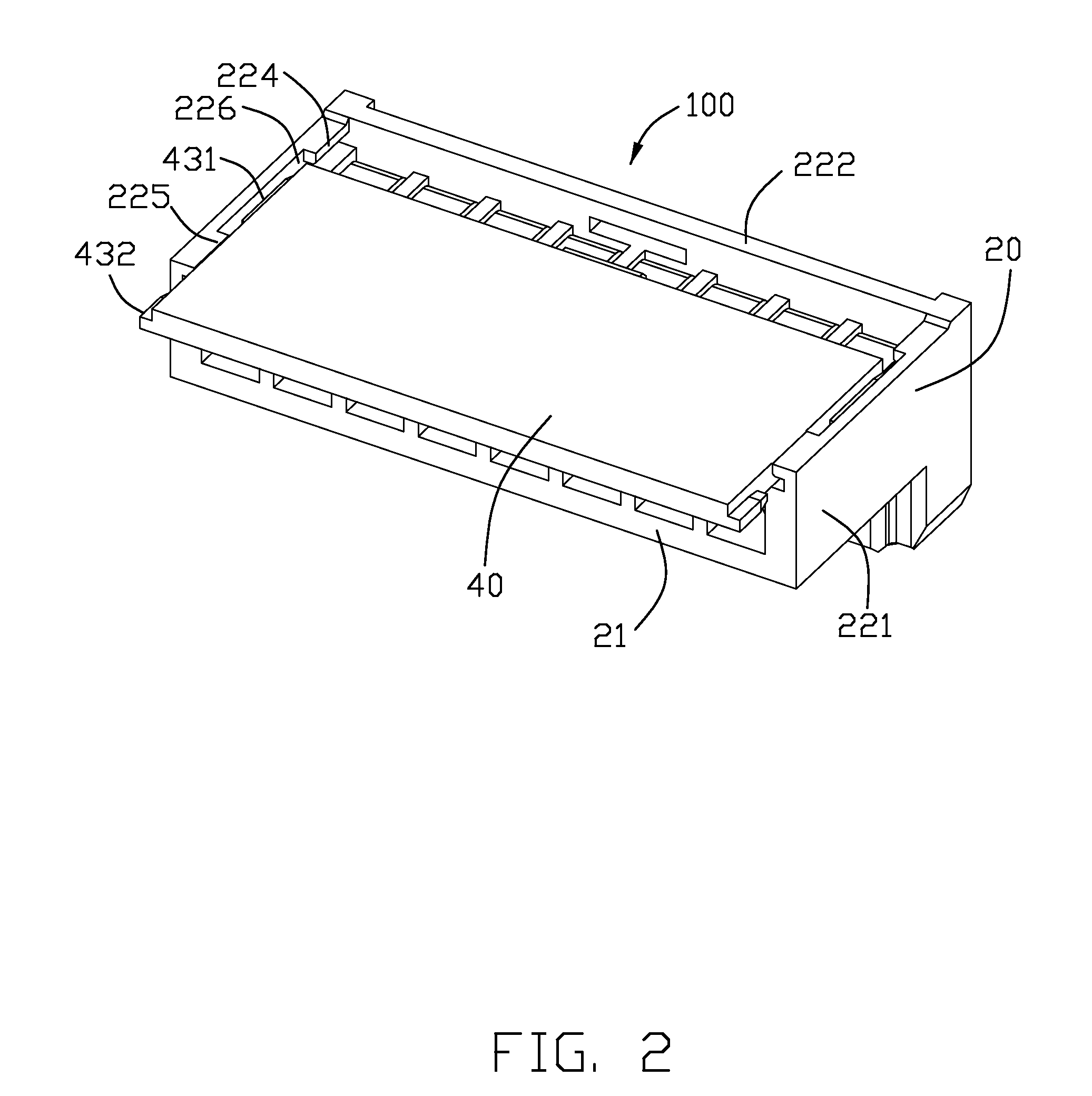
[0017]Reference will now be made to the drawing figures to describe a preferred embodiment of the present invention in detail. Referring to FIG. 1, an electrical connector 100 made according to the preferred embodiment of the present invention is provided and comprises an elongated insulative housing 20, a plurality of terminals 30 received in the insulative housing, a plurality of conductive wires 50 terminated to the terminals and a cover 40 detachably on the insulative housing for enclosing the terminals 30 and conductive wires 50.

[0018]Referring to FIGS. 3 and 4, the insulative housing 20 is in an elongated configuration and comprises a rectangular bottom wall 21, vertical side walls extending upward from the bottom wall 21 and a supporting rib 23 protruding downward along a longitudinal direction of the bottom wall 21. The side walls include a pair of opposite first side walls 221 face-to-face arranged and a second side wall 222 connecting the first side walls and located at a ...


PUM


Abstract

Provided is an electrical connector including an insulative housing having a main body and a supporting board extending downward from the main body so as to form an L shaped configuration. The main body defines a plurality of receiving passageways extending along a front-to-rear direction and then runs through the supporting board along a vertical direction. A pair of guiding grooves are respectively formed at opposite inner sides of the main body. A plurality of terminals are retained in the receiving passageways. A cover defines locking portions at opposite sides thereof for movably received in the guiding grooves and covers the terminals for preventing outward movement of the terminals.

Description

BACKGROUND OF THE INVENTION[0001]1. Field of the Invention[0002]The present invention relates an electrical connector, and more particularly to an electrical connector having a detachable cover attached to a housing thereof facilitating readily and laborious-fee assembling.[0003]2. Description of the Related Art[0004]Chinese Invention Patent No. 1992435A issued to Yotsutani on Jul. 4, 2007 discloses a cable assembly comprising an insulative housing with a plurality of terminals assembled therein and a cover assembled on the insulative housing for ensuring the reliable engagement between the terminals and cables terminated to the terminals. The insulative housing defines a receiving cavity surrounded by a pair of opposite side walls for receiving the terminals and cables. Each side wall forms an aperture at an upper side for receiving a protrusion formed at each opposite side of the cover, therefore the cover could not move in a front-to-back direction. However, as there is no retent...

Claims


Application Information

Patent Timeline
Patent Type & Authority Applications(United States)
IPC IPC(8): H01R9/03H01R9/22
CPCH01R9/03H01R13/506H01R24/20H01R13/112H01R2107/00
Inventor QIAN, ZHEN-HUA
Owner HON HAI PRECISION IND CO LTD
Why Eureka
Try Eureka