Patient Lifting Apparatus

a technology for lifting equipment and patients, applied in hospital equipment, nursing beds, medical science, etc., can solve problems such as muscle strain and other associated injuries, and patients may also be inadvertently injured

Inactive Publication Date: 2010-09-16
LEAR MEDICAL DEVICES
View PDF6 Cites 16 Cited by
  • Summary
  • Abstract
  • Description
  • Claims
  • Application Information

AI Technical Summary

Benefits of technology

[0017]A method of operating a patient lifting apparatus, the patient lifting apparatus including a main frame, a base support section, an upper section having a first and second spaced apart upper members, each upper member including a front and rear spaced apart pulley to provide a front and rear pair of pulleys, each pulley having a cable running there through, to form a front and rear set of cables, an...

Problems solved by technology

However, is quite common for hospital staff to become injured during such lifting efforts due to the weight of the patient as well as the lack of control in actually lifting and moving the pat...

Method used


Image

  • Patient Lifting Apparatus
  • Patient Lifting Apparatus
  • Patient Lifting Apparatus

Examples


Embodiment Construction

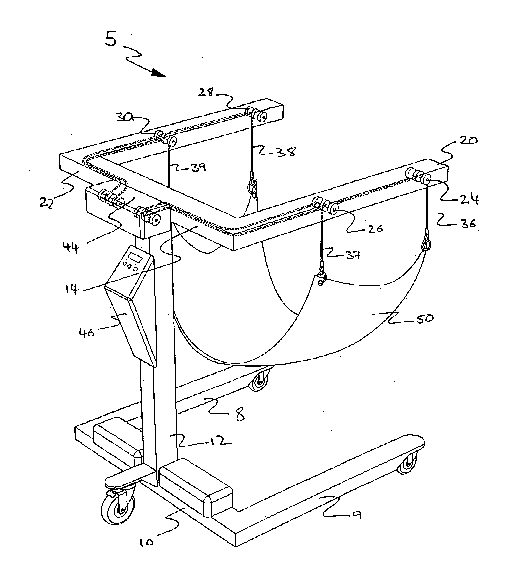
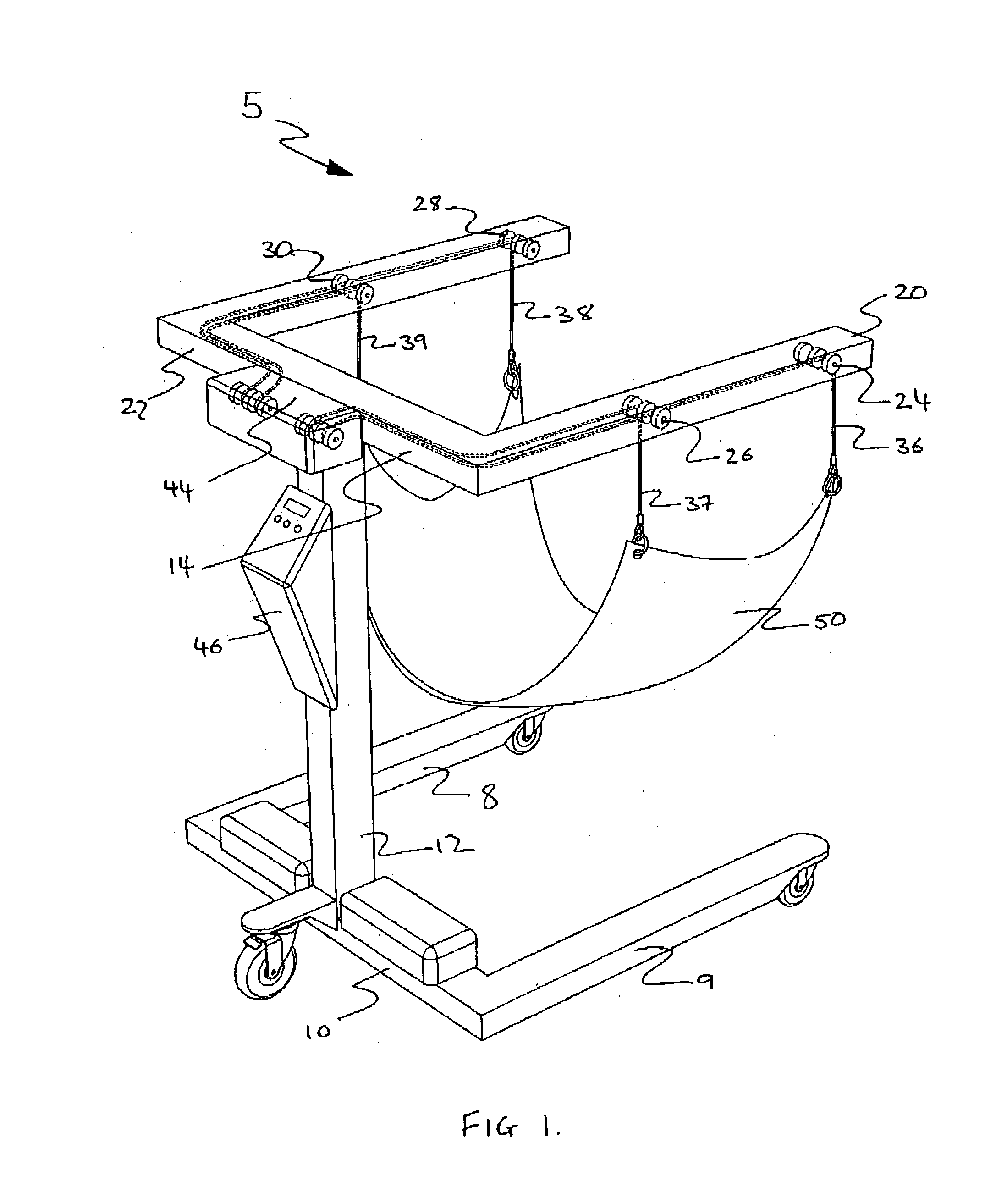
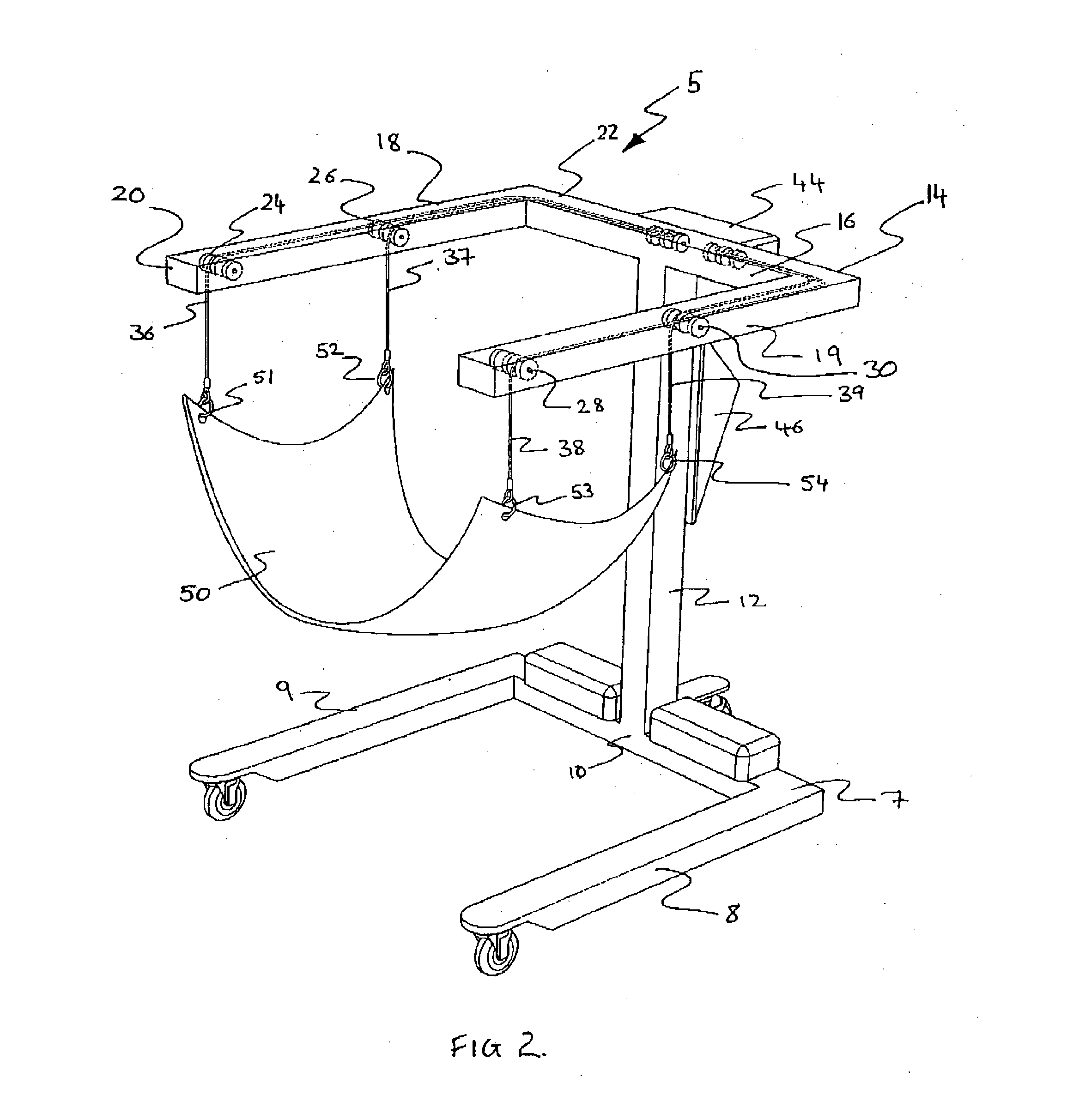
[0022]The patient lifting apparatus 5 includes a base support section 7 being in a generally “U”-shaped section, with parallel spaced apart legs 8 and 9 separated by the transverse member 10. Connected to the transverse member 10, approximately midway along its length, is the main upright support member 12 that in turn connects to an upper section 14.

[0023]The upper section 14 includes a transverse upper member 16 with first and second arms, 18 and 19 respectively, each arm having a front section 20 and rear section 22.

[0024]Each arm 18 and 19 has pulleys located within; for example, the first arm 18 has front pulley 24 and rear pulley 26 and the second arm 19 has a front pulley 28 and a rear pulley 30, such that there is effectively a front pair of pulleys 32 and a rear pair of pulleys 34. Each pulley is able to rotate about its axis although other pulley equivalent structures may be used to effect the same result and those skilled in the art would readily appreciate this.

[0025]Eac...


PUM


Abstract

A patient lifting apparatus that includes a front and rear independently controlled cable lowering means so that a patient sitting in a sling suspended from the cables can be assisted out of the sling, or into the sling depending on the situation. This provides great, and safer, control of patient movement that otherwise provided.

Description

FIELD OF THE INVENTION[0001]The field of the invention relates to apparatus and equipment for lifting and in particular, the lifting of human patients.DESCRIPTION OF THE PRIOR ART[0002]In hospitals and patient care facilities there is often a need for equipment designed to lift a person from one position to another full stop for example, it is often the case that a patient who is incapacitated may need to be lifted from their bed, in a lying down position, up and into a chair.[0003]Typically this is often itchy by the use of two and sometimes three orderlies or hospital staff specifically trained to efficiently and safely lift patients. Each staff member has a specific position relative to the patient and it is essential that each member coordinates their lifting efforts with the other staff member to affect a successful lift and transfer.[0004]However, is quite common for hospital staff to become injured during such lifting efforts due to the weight of the patient as well as the la...

Claims


Application Information

Patent Timeline
IPC IPC(8): A61G7/10
CPCA61G7/1015A61G7/1046A61G2200/34A61G7/109A61G7/1051
Inventor LEAR, ADAM THOMAS
Owner LEAR MEDICAL DEVICES
Why Eureka
Try Eureka