
Gas mask assembly with swivel connector

a technology of swivel connectors and gas masks, which is applied in the field of connecting devices, can solve the problems of inflexible connections to the mask manifold, air leakage, and gas leakage,

Inactive Publication Date: 2010-09-16
AUSTRALIAN CENT FOR ADVANCED MEDICAL TECH
View PDF12 Cites 43 Cited by
  • Summary
  • Abstract
  • Description
  • Claims
  • Application Information

AI Technical Summary

Benefits of technology

[0013]This invention provides connectors for attachment of gas supply lines to gas mask assemblies and which allows the supply line to move relative to the mask and without placing unwanted load lateral, torsional or otherwise. The invention further provides at least one swivel joint connector in a gas supply line to such mask assemblies and which allows 360 degree axial rotation of a line about a longitudinal axis through the supply line and / or swivel movement of the line relative to the mask and at an angle to that axis and in more than one plane.
[0026]a swivel connector for a gas delivery assembly including a face mask having a manifold, a face contacting portion which engages the face of a wearer, means to fasten the mask to a face of a wearer and an inlet which allows delivery of gas from a gas source to the inside of said manifold; the assembly further comprising a gas delivery line communicating between the gas source and said manifold; wherein the delivery line is connected to the manifold via the swivel connector which allows 360 degree axial rotation of the line about a longitudinal axis through the supply line and / or swivel movement of the line relative to the mask.
[0032]More specifically the swivel connector allows axial loading about an axis through the line when a mask moves and rotational movement in an X axis plane and a Z axis plane. The use of a swivel connection relieves the effect of such loadings helping to maintain seal integrity.
[0033]Preferably the manifold shell, mask shape forming elements, side walls and face contacting elements and gas inlet are integrally moulded in one piece from an elastomeric material such as silicone rubber. The mask is also preferably sufficiently flexible to enable a patient to remove it or fix it in position without having to adjust any harness connection points where a harness connects to the straps of the mask. The face contacting portion of the mask typically defines an inwardly curving gas sealing surface which in use contacts the patient's face.
[0034]It is preferred that the manifold is flexible enough to collapse toward the patients nose when a moderate external force is applied to it, to allow, for example, a patient to scratch their nose without removing the mask. With the mask in situ, the manifold can be distorted onto the patient's nose without breaking the airtight seal between the face contacting element and the patients skin. This also means that when a patient turns in sleep and their mask contacts a pillow or some other object the manifold will deform rather than be pushed against the patient's face. The aforesaid geometry and consequent sealing arrangements of the known masks is further enhanced by use of at least one swivel connection assembly in the connection of the gas line to the manifold and connection of the opposite end of the line to a gas supply manifold via at least one other swivel connector.

Problems solved by technology

These movements have in the past moved rigid masks to a point where a seal is broken and contributing to this is the inflexibility of the connections to the mask manifold.
When a patient wearing a mask having a rigid manifold turns in bed and contacts an object such as a pillow, reaction forces from the pillow tend to push the manifold laterally and lift the face contacting part from the patient's face thereby breaking the gas tight seal and causing an air leak which prevents optimum therapy being delivered to the patient.
Hard plastic components may also cause pain or discomfort if they are pushed hard against a patient's skin during sleep.
This allows the line some limited flexibility to move relative to the mask when a wearer of the mask moves.

Method used


Image

  • Gas mask assembly with swivel connector
  • Gas mask assembly with swivel connector
  • Gas mask assembly with swivel connector

Examples


Embodiment Construction

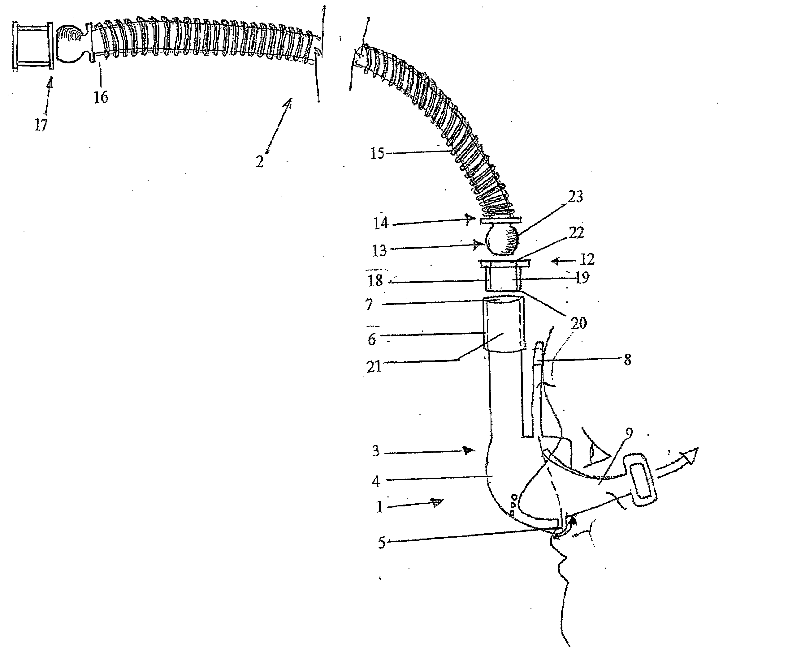
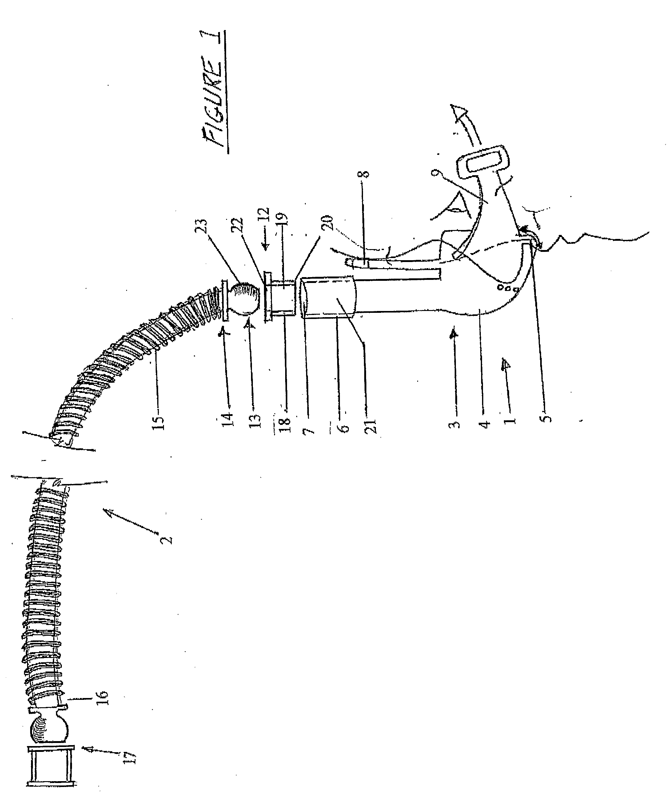
[0057]Referring to the drawings, FIG. 1 shows an elevation view of a first embodiment of a typical mask assembly 1 including swivel connector assembly 2. The mask 3 shown is designed for pressurised gas delivery to a patient's nose only.

[0058]Mask 3 is preferably integrally moulded in a single piece from a flexible elastomeric material, most preferably a medical grade silicone, however, any suitable elastomeric material may be used. Mask 3 includes a flexible central manifold 4, a flexible integral face contacting portion 5 and an annular air inlet pipe 6 extending away from the manifold 4 to a generally cylindrical outlet 7 at a distal end of the air inlet pipe 6.

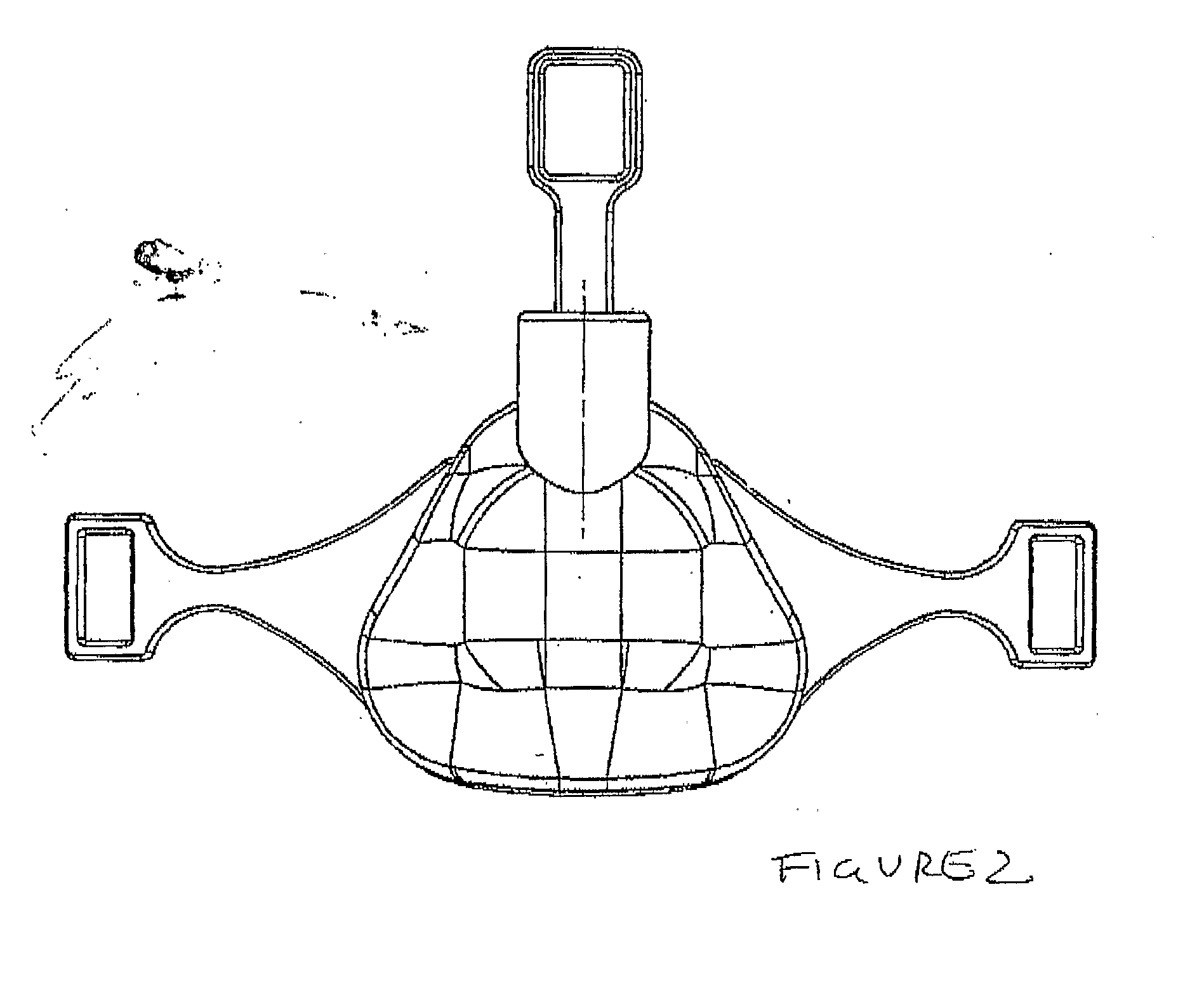
[0059]Mask 3 will typically include a nasal bridge strap 8 extends away from the top of the manifold 4. Two straps 9, 10 extend away from opposite sides of the manifold in a direction which is generally perpendicular to the longitudinal axis of the nasal bridge strap 8. The wall thickness of the manifold and face contactin...


PUM


Abstract

A connection assembly for joining a gas supply line to an article, the assembly comprising a first member having first and second ends, inner and outer walls; and a through passage between said ends; a second member having first and second ends, the second end engagable with the first member via the first end of the first member, the second end of the first member connectable to the article and the first end of the second member connectabte to a gas line; wherein the connection between the first and second members is arranged to allow relative movement between the first and second members such that either of the first and second members are each able to rotate axially relative to the other member through a 360 degrees arc about longitudinal axes through each member and to each move relative to the other member between a first disposition where the longitudinal axes of the first and second members are in alignment and at least one second disposition where at least the second member is disposed at an angle to the longitudinal axis of the first member.

Description

FIELD OF THE INVENTION [0001]This invention relates to connectors for attachment of gas supply lines to gas mask assemblies and in particular, to masks for supplying gases, typically air or oxygen, to the airways (nose and / or mouth) of humans. Such masks are often referred to as “respirator masks” and are particularly suited to applying continuous positive airway pressure (CPA) to patients for a variety of treatments. More particularly, the invention relates to gas supply line connection arrangements for a mask assembly which includes a manifold section having a face contacting part and an inlet connecting to the manifold and a gas supply line connected to the inlet. The invention provides at least one swivel joint connector in a gas supply line to such mask assemblies and which allows 360 degree axial rotation of a line relative to a mask about a longitudinal axis through the supply line and swivel movement of the line relative to the mask at an angle to the longitudinal axis of th...

Claims


Application Information

Patent Timeline
IPC IPC(8): A62B18/08
CPCA61M16/06A61M16/08A61M16/0825F16L27/04A61M16/0875A61M2205/0216
Inventor SULLIVAN, COLIN
Owner AUSTRALIAN CENT FOR ADVANCED MEDICAL TECH
Features
  • Generate Ideas
  • Intellectual Property
  • Life Sciences
  • Materials
  • Tech Scout
  • Unparalleled Data Quality
  • Higher Quality Content
  • 60% Fewer Hallucinations
Learn More