Micro-fluid ejection heads and methods for bonding substrates to supports

a technology of microfluid ejection and substrate, which is applied in the direction of adhesive processes, adhesive processes with surface pretreatment, printing, etc., can solve the problems of affecting the position and alignment of the microfluid ejection head components, the ejection head continues to evolve and become larger, and the ejection head may be affected by significant mismatches, so as to reduce the cost of materials, avoid the effect of heat curing steps and avoiding mismatches

Active Publication Date: 2010-09-16
FUNAI ELECTRIC CO LTD
View PDF2 Cites 0 Cited by
  • Summary
  • Abstract
  • Description
  • Claims
  • Application Information

AI Technical Summary

Benefits of technology

[0014]An advantage of the structures and method of the present disclosure is that bond may be formed at a relatively low temperature, thus eliminating heat curing steps of the presently used die-bonding adhesive methods that may result in bowing or warping of the device substrate and nozzle plate due to CTE mismatch between the different materials. In the presently disclosed structure and method, a thinner silicon wafer may be used for the device substrate than with conventional manufacturing techniques, thereby providing a reduction in materials cost for producing micro-fluid ejection devices. Another advantage of the present disclosure is that a covalent bond between the device substrate and the support material provides a hermetic seal that is not susceptible to attack or degradation by fluids such as ink, unlike adhesive die-bonding materials.

Problems solved by technology

As the capabilities of micro-fluid ejection devices are increased to provide higher ejection rates, the ejection heads, which are the primary components of micro-fluid ejection devices, continue to evolve and become larger, more complex, and more costly to manufacture.
The position and alignment of the micro-fluid ejection head components may be affected by significant mismatches in coefficients of thermal expansion (“CTE”) between the various members of the ejection head, including the nozzle plate, the device substrate, the base support, and any adhesive material used in securing the aforementioned components to one another.
However, such adhesive requires thermal curing which may cause expansion and contraction of the components and may lead to warping or bowing of the ejection device substrate and the nozzle plate.
However, current manufacturing processes are limited by the size of the ejection chip.

Method used


Image

  • Micro-fluid ejection heads and methods for bonding substrates to supports
  • Micro-fluid ejection heads and methods for bonding substrates to supports
  • Micro-fluid ejection heads and methods for bonding substrates to supports

Examples


Embodiment Construction

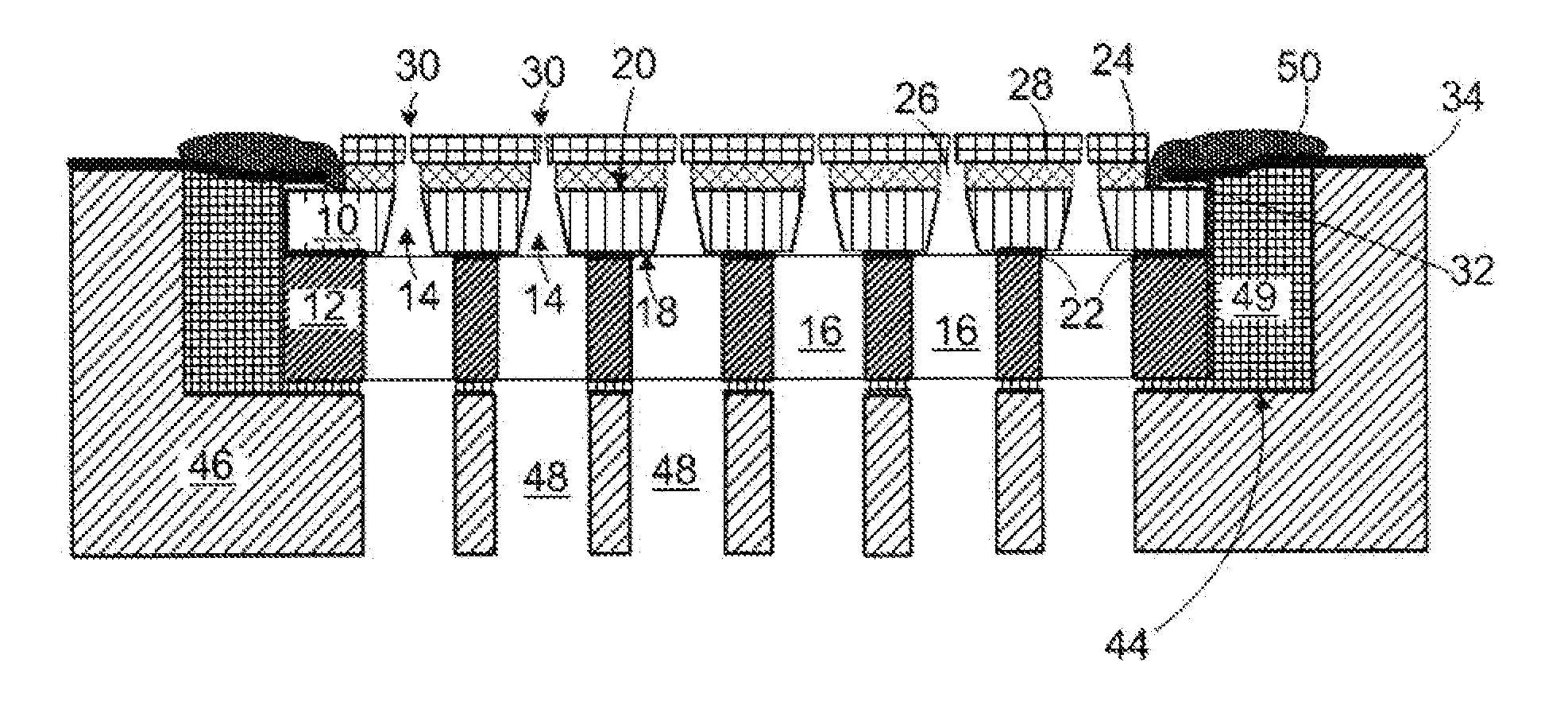
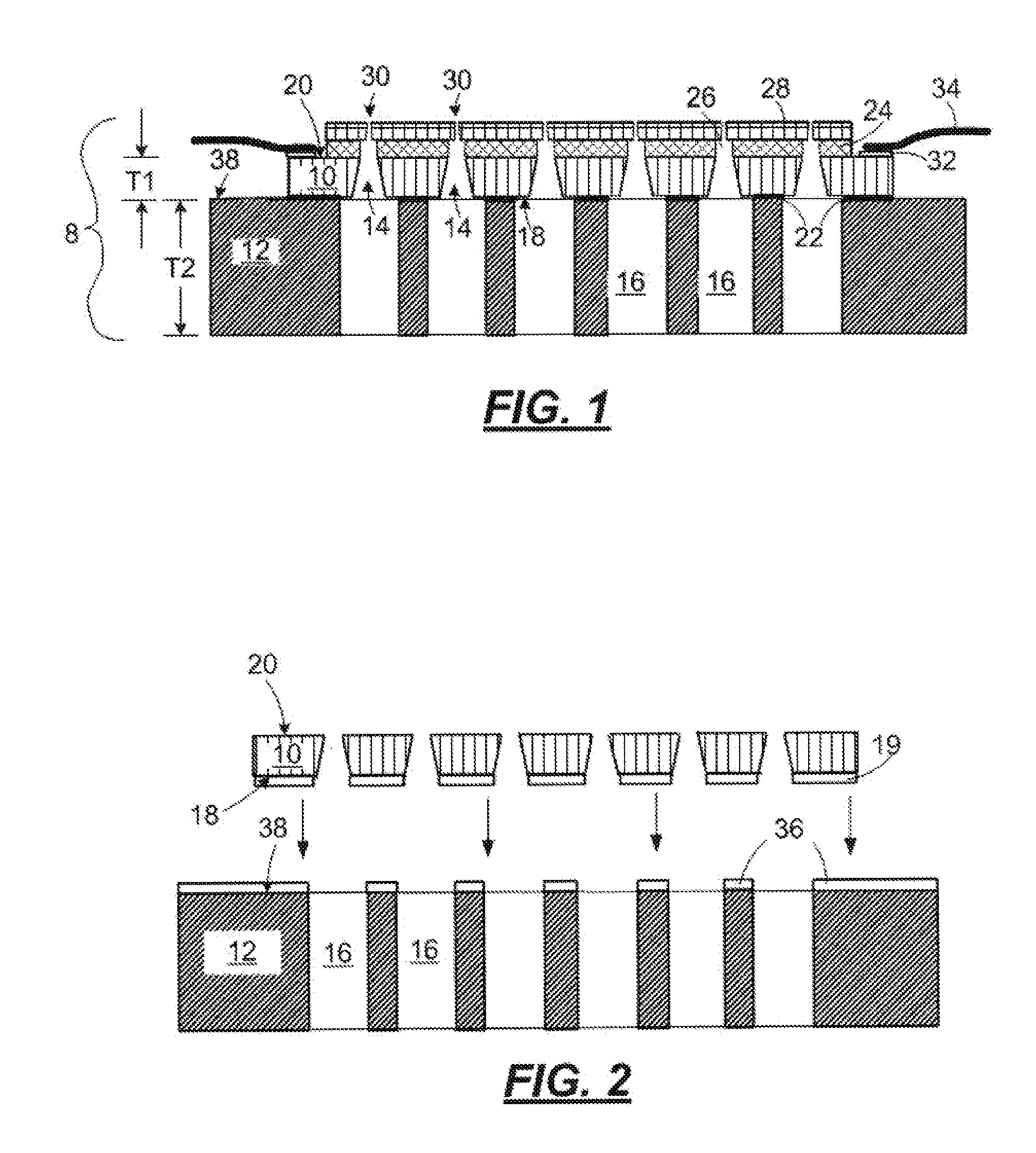
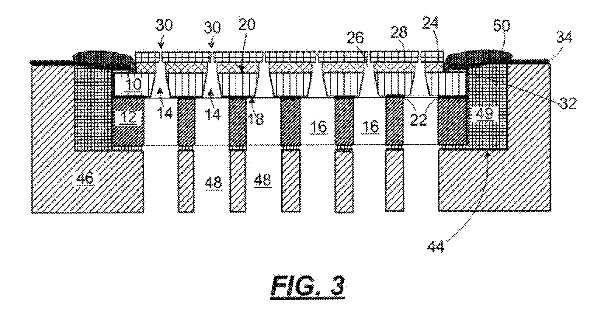
[0020]With reference to FIG. 1, the present disclosure is directed to a substantially planar micro-fluid ejection head 8 comprising a device substrate 10 and a support material 12. The device substrate 10 has at least one fluid flow slot 14 formed therein. The support material 12 has at least one fluid flow slot 16 formed therein that corresponds to the slot 14 on the device substrate 10. The device substrate 10 additionally has a first surface 18 and a second surface 20 opposite the first surface. The first surface 18 of the device substrate 10 is hermetically bonded to the support material 12 at one or more points of contact 22 between the device substrate 10 and the support material 12.

[0021]The device substrate 10 may further comprise a layer of flow feature material 24 attached adjacent to the second surface 20 of the device substrate 10. The flow feature material 24 has at least one fluid flow channel and chamber 26 formed therein that corresponds to the slot 14 in the device ...


PUM

PropertyMeasurementUnit
pressureaaaaaaaaaa
temperatureaaaaaaaaaa
pressureaaaaaaaaaa

Abstract

A substantially planar micro-fluid ejection device, where the micro-fluid ejection head is hermetically sealed and bonded to a support material, and a method of bonding a silicon device, such as a micro-fluid ejection head, to a support material.

Description

[0001]This application claims priority and benefit as a divisional application of U.S. patent application Ser. No. 11 / 848,246, filed Aug. 31, 2007.TECHNICAL FIELD[0002]The disclosure relates to a micro-fluid ejection head and, in a particular exemplary embodiment, to a silicon structure for a device, such as a micro-fluid ejection head, hermetically sealed and bonded to a support material, where neither the bonded surface of the ejection head nor the bonded surface of the support material are required to be substantially planar.BACKGROUND AND SUMMARY[0003]Micro-fluid ejection devices such as ink jet printers continue to experience wide acceptance as economical replacements for laser printers. Micro-fluid ejection devices also are finding wide application in other fields such as in the medical, chemical, and mechanical fields. As the capabilities of micro-fluid ejection devices are increased to provide higher ejection rates, the ejection heads, which are the primary components of mic...

Claims


Application Information

Patent Timeline
Patent Type & Authority Applications(United States)
IPC IPC(8): C09J5/02
CPCB41J2/16B41J2/1623B41J2/1642B41J2/1645B41J2/1646Y10T29/49002C09J5/02C09J2400/146Y10T29/42Y10T156/1056Y10T29/49401B41J2002/14491
Inventor BERNARD, DAVID LAURIERDRYER, PAUL WILLIAMMCNEES, ANDREW LEE
Owner FUNAI ELECTRIC CO LTD
Why Eureka
Try Eureka