Vehicular impact bumper assembly

a technology for impact bumpers and suspension systems, which is applied in the direction of shock absorbers, mechanical equipment, transportation and packaging, etc., can solve the problems of reducing the impact load cushioning effect of the impact load, and reducing the impact load

Inactive Publication Date: 2010-09-16
GM GLOBAL TECH OPERATIONS LLC
View PDF15 Cites 31 Cited by
  • Summary
  • Abstract
  • Description
  • Claims
  • Application Information

AI Technical Summary

Benefits of technology

[0005]In accordance with an embodiment, by way of example only, an impact bumper assembly for a vehicle is provided. The assembly comprises a first member, and a second member coupled to the first member and configured for relative motion therewith. The assembly also comprises a resilient bumper coupled to the first member and interposed between the first and second members, wherein the resilient bumper has an annular wall having a plurality of openings therethrough, and wherein the resilient bumper is configured to deform axially without substantial radial deformation when compressed between the first and second members.

Problems solved by technology

However, severe impact events can impose excessive loading on a suspension causing it to contract beyond the designed operating range of springs and shocks / struts.
Excessive jounce, or downward motion of the body toward the chassis, can lead to potentially damaging collisions between suspension components and / or other undercarriage elements.
However, such a configuration provides little cushioning effect from impact loads because of the rigidity of the striker plate and the marginal capacity of the foam rubber bumper to absorb associated energy.
As a result, striker plates, jounce bumper mounts, body structure, frame structure, and / or other structural elements can receive the brunt of impact loads making them susceptible to damage.
Such a design adds to the overall weight and expense of damper assemblies, and reduces their space efficiency.

Method used


Image

  • Vehicular impact bumper assembly
  • Vehicular impact bumper assembly
  • Vehicular impact bumper assembly

Examples


Embodiment Construction

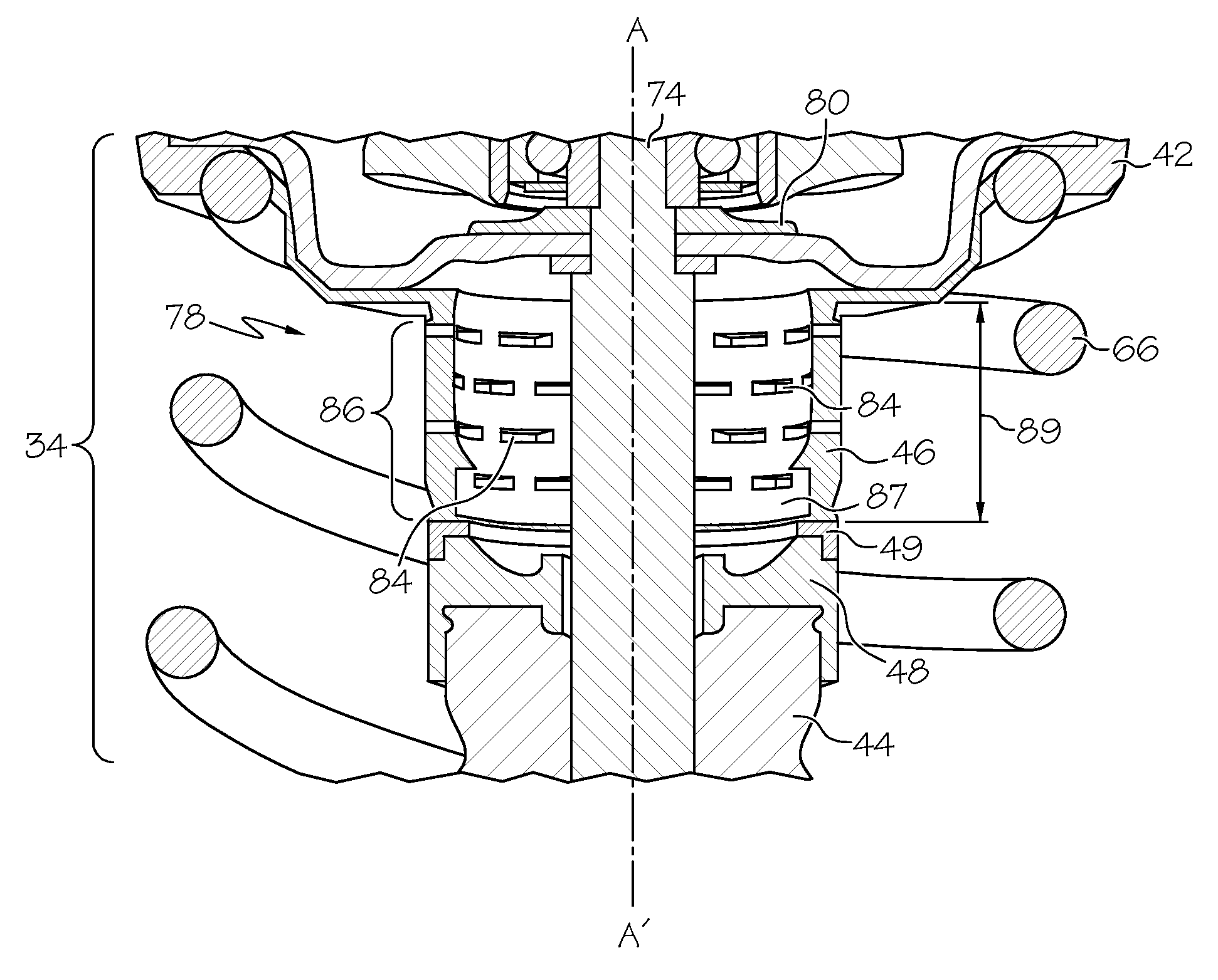
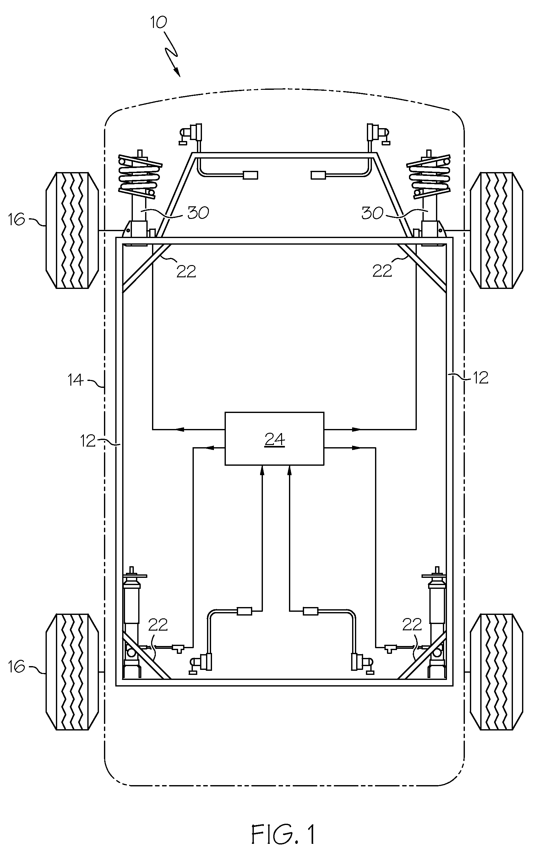
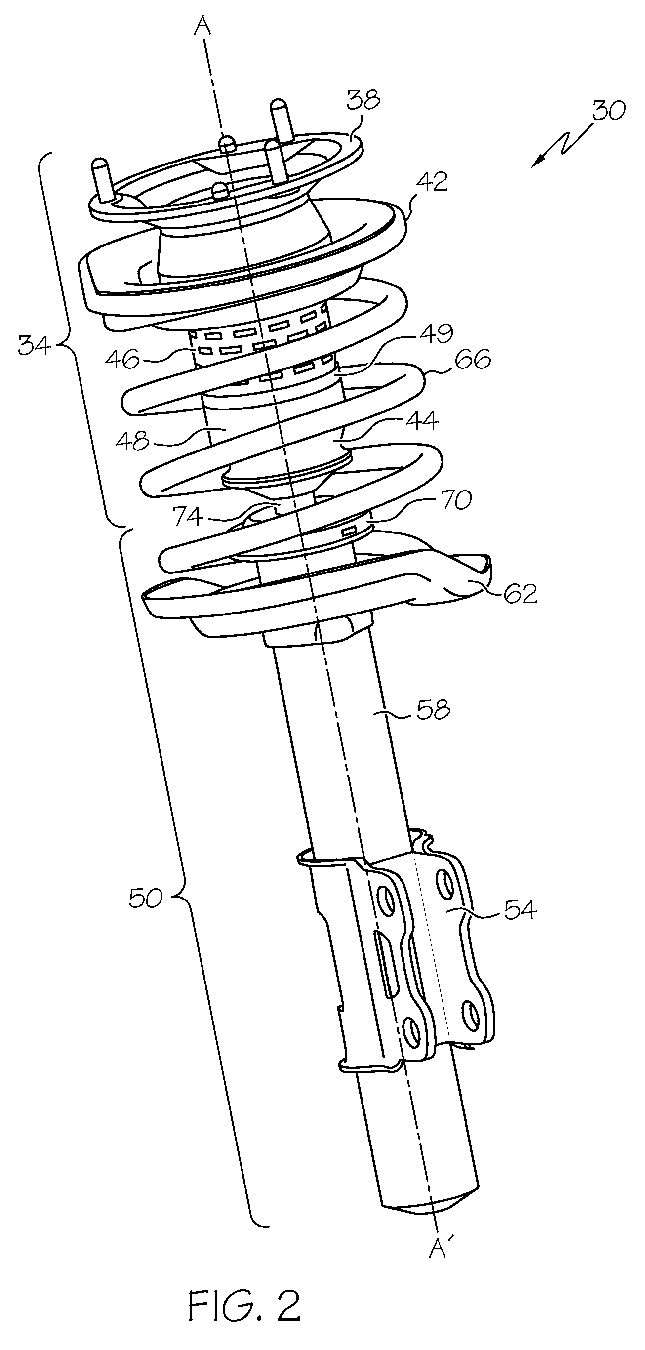
[0012]The various embodiments of the present invention described herein provide an impact bumper assembly integrated between two suspension members for managing impact load for a vehicular suspension. The assembly is configured to absorb energy during impact events characterized by excessive contractive relative motion between the body and chassis of a vehicle (jounce), and may be mounted between suitable suspension members wherein it is desirable to limit such excessive jounce motion. The assembly may be used in a standalone manner, or may be integrated within the body of a damper assembly such as a shock absorber or a strut. The assembly includes a resilient annular impact bumper coupled between two suitable suspension members and configured to compress axially during impacting events, absorbing energy from the impact load thereby, without substantial radial deformation. The radial geometric stability of the impact bumper during axial deformation also improves the space efficiency...


PUM


Abstract

An impact bumper assembly for a vehicle is provided. The assembly comprises a first member, and a second member coupled to the first member and configured for relative motion therewith. The assembly also comprises a resilient bumper coupled to the first member and interposed between the first and second members, wherein the resilient bumper has an annular wall having a plurality of openings therethrough, and wherein the resilient bumper is configured to deform axially without substantial radial deformation when compressed between the first and second members.

Description

TECHNICAL FIELD[0001]The present invention generally relates to vehicular suspension systems, and more particularly relates to an impact bumper assembly for a vehicular suspension system.BACKGROUND OF THE INVENTION[0002]Vehicles are typically equipped with suspension systems that generally include a multitude of springs, linear actuators, damper assemblies such as shock absorbers and / or struts, interconnecting support members, and the like that compress and expand to provide flexible relative movement between the body and chassis. During normal driving conditions, these components gradually dissipate the forces generated by bumps, potholes, and other road conditions in a controlled manner that maintains passengers in a safe and comfortable driving environment.[0003]However, severe impact events can impose excessive loading on a suspension causing it to contract beyond the designed operating range of springs and shocks / struts. Excessive jounce, or downward motion of the body toward t...

Claims


Application Information

Patent Timeline
Patent Type & Authority Applications(United States)
IPC IPC(8): F16F11/00
CPCF16F1/377
Inventor SCHUDT, JOSEPH A.POIRIER, DARYL R.PATIL, RAVINDRA P.GEISLER, ROBERT L.
Owner GM GLOBAL TECH OPERATIONS LLC
Why Eureka
Try Eureka