Pivot-Steered Vehicle

Inactive Publication Date: 2010-09-16
BOMAG
View PDF14 Cites 4 Cited by
  • Summary
  • Abstract
  • Description
  • Claims
  • Application Information

AI Technical Summary

Benefits of technology

[0009]An easy-to-use, pivot-steered vehicle is provided, in which, despite a shortened overall length, it is possible to set a large steering angle without the frame edges abutting one another during the steering process and without the volumes of the vehicle frames being reduced in size, so that there is sufficient space for arranging ma-chine components.
[0023]The described crosswise connection with four rotary joints and two connecting members in two planes allows a compact, robust and maintenance-friendly design of the pivot steering gear. It goes without saying that, in addition to the preferred exemplary embodiment which has been described in detail, an alternative implementation of the pivot steering gear is also possible in which, for example via mechanical or electromagnetic closing mechanisms, alternately only one pair of rotary joints is engaged, i.e. forms the pivot axis, and the opposing pair of rotary joints is released for swiveling.

Problems solved by technology

If a larger steering angle is striven for in order to improve maneuverability, this inevitably increases the size of the free space between the frame edges in which the pivot joint is located, giving rise to a broad range of drawbacks.
On the one hand, the total length of the vehicle is increased in size; this can present difficulties during transportation, etc.
Furthermore, the increase in the size of the spacing between the vehicle frames is also associated with increased consumption of materials.
A disadvantage of the principle applied in the pivot steering of this vehicle is that the adjustment apparatus for steering the vehicle necessarily entails a relatively large amount of construction room in the longitudinal direction of the vehicle.
It is also disadvantageous that a separate adjustment device, for example a hydraulic cylinder, is required for creating a pivoting movement about each swivel axis, which increases the cost and decreases the effectiveness of the steering apparatus.

Method used


Image

  • Pivot-Steered Vehicle
  • Pivot-Steered Vehicle
  • Pivot-Steered Vehicle

Examples


Embodiment Construction

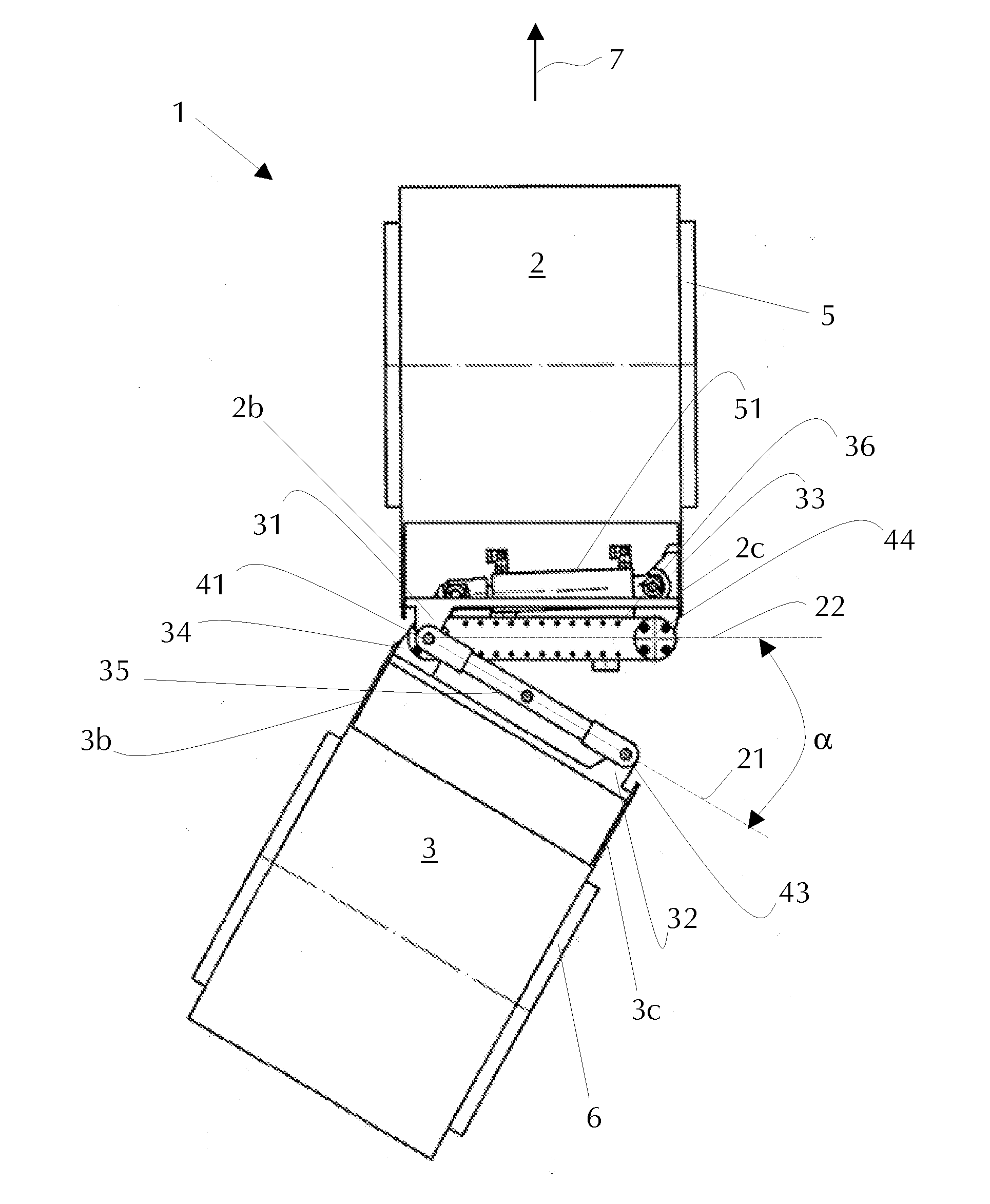
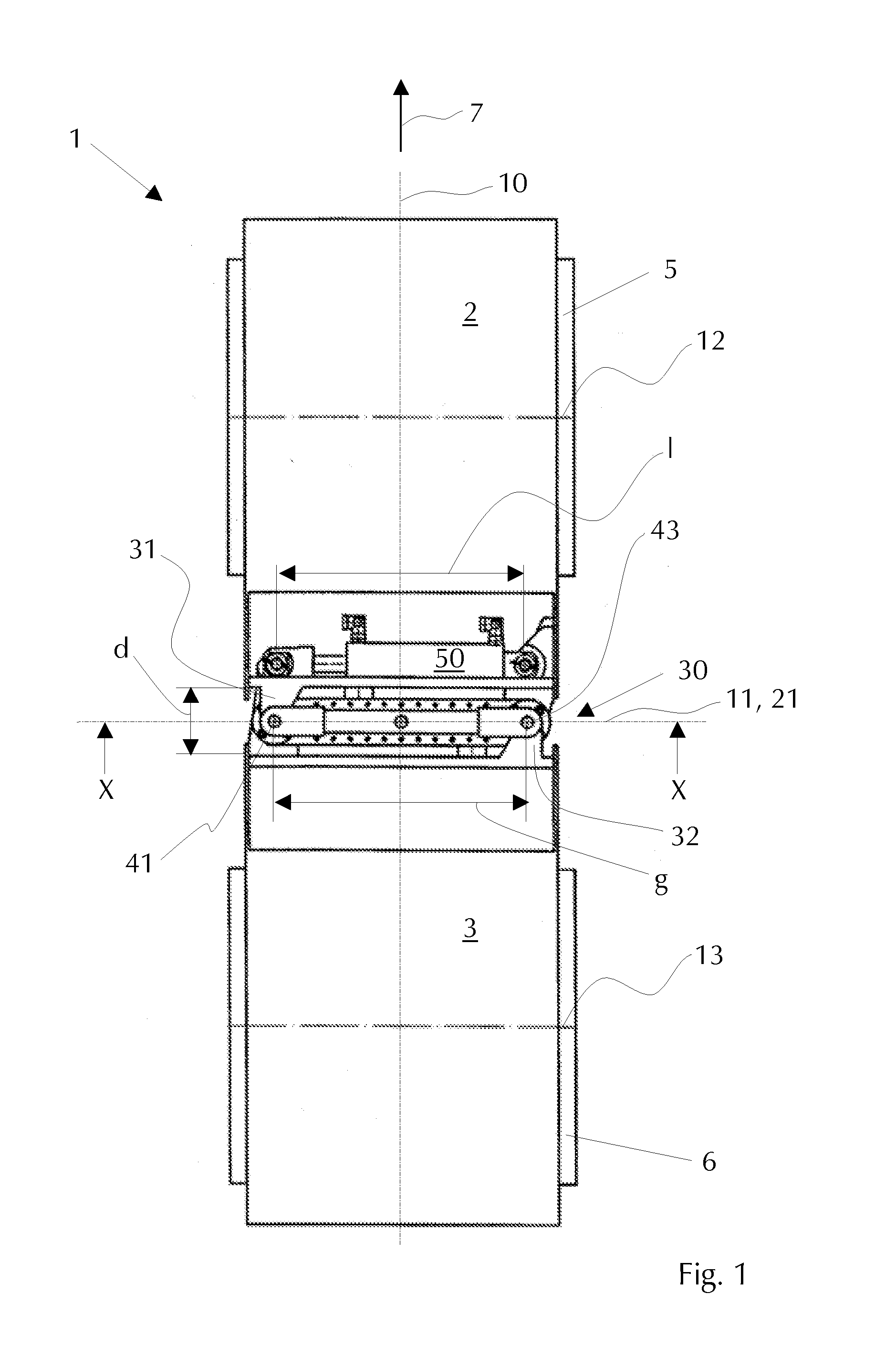
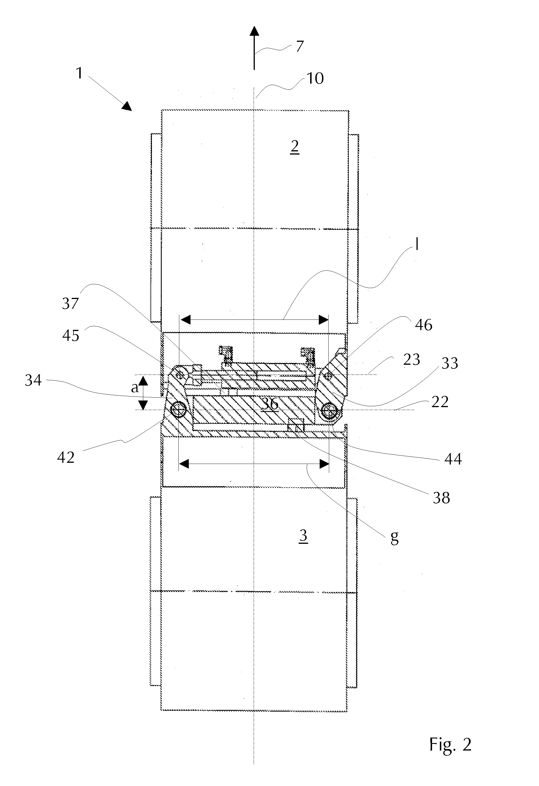
[0044]FIGS. 1 and 2 are plan views onto an exemplary embodiment of the vehicle 1 according to an embodiment of the invention in the neutral position. The illustrated vehicle 1 is a soil compaction roller, in particular a trench roller, with vibration and travel drive, with a front frame 2 and a rear frame 3. The front frame 2 has a front tire 5 having a front axis 12. Accordingly, the rear frame 3 comprises a rear tire 6 having a rear axis 13. The vibratory roller 1 shown is constructed substantially symmetrically to the longitudinal centre axis 10 and to the transverse axis 11. The pivot steering gear 30 connects the front frame 2 and the rear frame 3 in two horizontal planes E1, E2 in an articulated manner and crosswise to each other.

[0045]FIG. 1 clearly shows the first horizontal plane E1 of the pivot steering gear 30 with the upper rotary joints 41, 43. The two upper rotary joints 41, 43 are positioned set apart from each other by a spacing “g” and symmetrically opposing each ot...


PUM


Abstract

A pivot-steered vehicle, in particular a pivot-steered construction vehicle or machine, is provided. The vehicle includes a front frame and a rear frame which are connected to each other via a pivot steering gear and a steering drive. The pivot steering gear has a first and a second vertical pivot axis which are arranged opposing each other with respect to a longitudinal axis of the vehicle in a neutral position, the pivot steering gear being embodied in a first steering range for relative swiveling of the front frame and the rear frame about the first pivot axis and in a second steering range for relative swiveling of the front frame and the rear frame about the second pivot axis, the first and the second steering ranges being separated from each other via the neutral position.

Description

CROSS-REFERENCE TO RELATED APPLICATIONS[0001]This application claims priority to foreign patent application DE 10 2009 007092.3, filed on Feb. 2, 2009, the disclosure of which is incorporated herein by reference in its entirety.FIELD OF THE INVENTION[0002]The present invention relates to a pivot-steered vehicle, in particular, a pivot-steered construction vehicle or machine.BACKGROUND OF THE INVENTION[0003]Outstanding maneuverability and turnability, based on comparatively large steering angles and small turning radii, have helped to establish pivot steering as a type of steering in vehicles with at least two vehicle frames each having at least one rigid axle. In particular construction vehicles, such as for example a vibratory rollers with two vehicle frames in each of which a tire is mounted, are often controlled with the aid of pivot steering.[0004]Conventional pivot-steered vehicles frequently use a central pivot joint which connects the two vehicle frames on the axis of symmetr...

Claims


Application Information

Patent Timeline
IPC IPC(8): B62D12/00B62D5/00
CPCB62D12/00
Inventor PONSTEIN, JOACHIM
Owner BOMAG
Why Eureka
Try Eureka