Apparatus and a method for generating a test case
a test case and apparatus technology, applied in the field of apparatus and a method for generating a test case, can solve the problems of not having a reasonable method not having a means for determining the state map, and often redundant test cases acquired from the state-transition system
- Summary
- Abstract
- Description
- Claims
- Application Information
AI Technical Summary
Benefits of technology
Problems solved by technology
Method used
Image
Examples
first embodiment
The First Embodiment
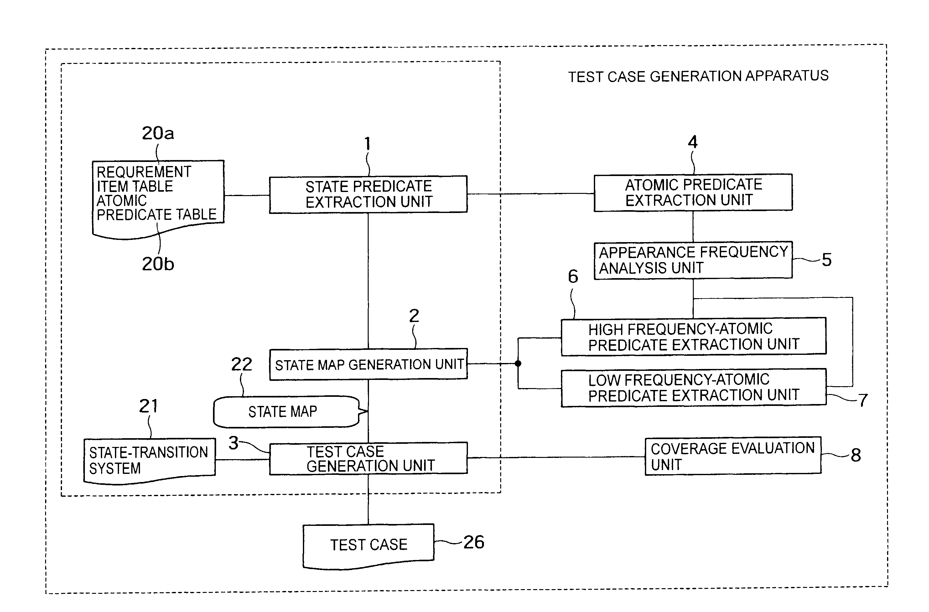
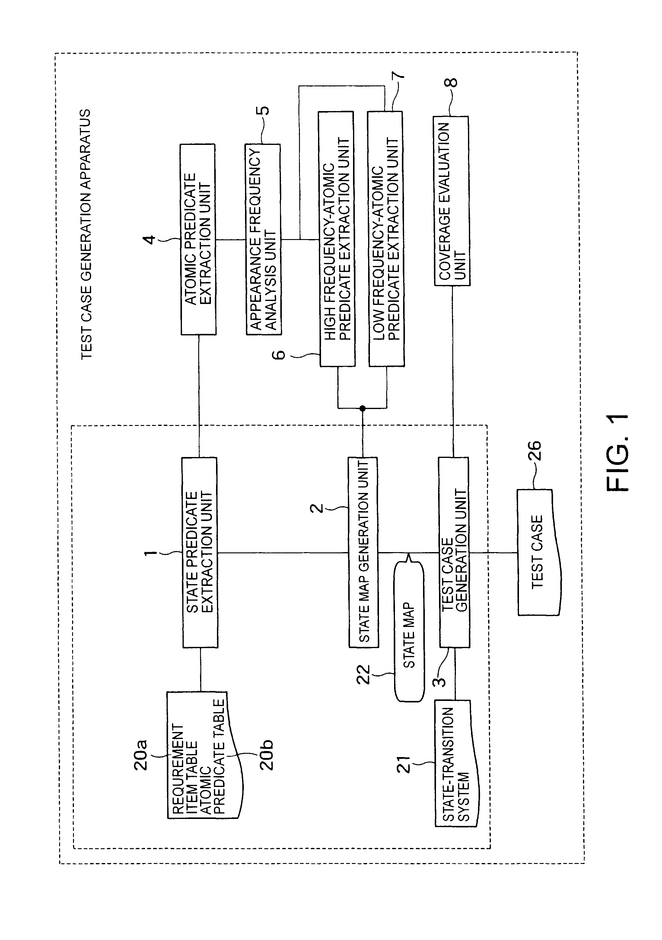
[0100]Apparatus component of the first embodiment corresponds to a part surrounded by an inside dotted line in FIG. 1. All apparatus surrounded by an outside dotted line is a component related to the second and third embodiments explained afterwards. Component of a part surrounded by the inside dotted line includes a state predicate extraction unit 1, a state map generation unit 2, a test case generation unit 3, a first memory to store a state-transition system 21, a second memory to store a requirement item table 20a and an atomic predicate table 20b, and an output unit to output a test vase 26. Hereinafter, the first embodiment is explained in detail.
1. Summary of the Apparatus
[0101]A state-transition system composed by states and state-transitions (each possible for a system to be checked) is previously prepared. Furthermore, as a combination of an external event of the system, a precondition and postcondition expected for the system, a plurality of requiremen...
second embodiment
The Second Embodiment
[0142]Apparatus component of the second embodiment corresponds to a part (except for the unit 7) surrounded by an outside broken line in FIG. 1. As to the component of the second embodiment, units 4˜6 and 8 are added to the component of the first embodiment. Briefly, the component of the second embodiment includes the state predicate extraction unit 1, the state map generation unit 2, the test case generation unit 3, the first memory to store the state-transition system 21, the second memory to store the requirement item table 20a and the atomic predicate table 20b, the output unit to output the test case 26, an atomic predicate extraction unit 4, an appearance frequency analysis unit 5, a high frequency-atomic predicate extraction unit 6, and a coverage evaluation unit 8.
1. Summary of Apparatus
[0143]Based on the first embodiment, a method for constructing the state map is extended. As to the method for constructing a state map according to the second embodiment...
third embodiment
The Third Embodiment
[0204]Apparatus component of the third embodiment corresponds to a part (except for the unit 6) surrounded by an outside broken line in FIG. 1. As to the component of the second embodiment, the unit 6 is deleted from and the unit 7 is added to the component of the second embodiment. Briefly, the component of the third embodiment includes the state predicate extraction unit 1, the state map generation unit 2, the test case generation unit 3, the first memory to store the state-transition system 21, the second memory to store the requirement item table 20a and the atomic predicate table 20b, the output unit to output the test case 26, the atomic predicate extraction unit 4, an appearance frequency analysis unit 5, a low frequency-atomic predicate extraction unit 7, and the coverage evaluation unit 8. As to each unit having the same name used in the second embodiment, its operation is basically same as that of the second embodiment. However, processing of the state ...
PUM
 Abstract
Description
Claims
Application Information
 - R&D
- Intellectual Property
- Life Sciences
- Materials
- Tech Scout
- Unparalleled Data Quality
- Higher Quality Content
- 60% Fewer Hallucinations
Browse by: Latest US Patents, China's latest patents, Technical Efficacy Thesaurus, Application Domain, Technology Topic, Popular Technical Reports.
© 2025 PatSnap. All rights reserved.Legal|Privacy policy|Modern Slavery Act Transparency Statement|Sitemap|About US| Contact US: help@patsnap.com


