Method for detecting fiber optic fibers and ribbons

Inactive Publication Date: 2010-09-23
AFL COMM LLC
View PDF47 Cites 17 Cited by
  • Summary
  • Abstract
  • Description
  • Claims
  • Application Information

AI Technical Summary

Problems solved by technology

One limitation of current optical fiber identification techniques is that the source can only be connected to one fiber at a time.

Method used


Image

  • Method for detecting fiber optic fibers and ribbons
  • Method for detecting fiber optic fibers and ribbons
  • Method for detecting fiber optic fibers and ribbons

Examples


Embodiment Construction

[0031]Hereinafter, exemplary embodiments of the present invention will be described with reference to the accompanying drawings.

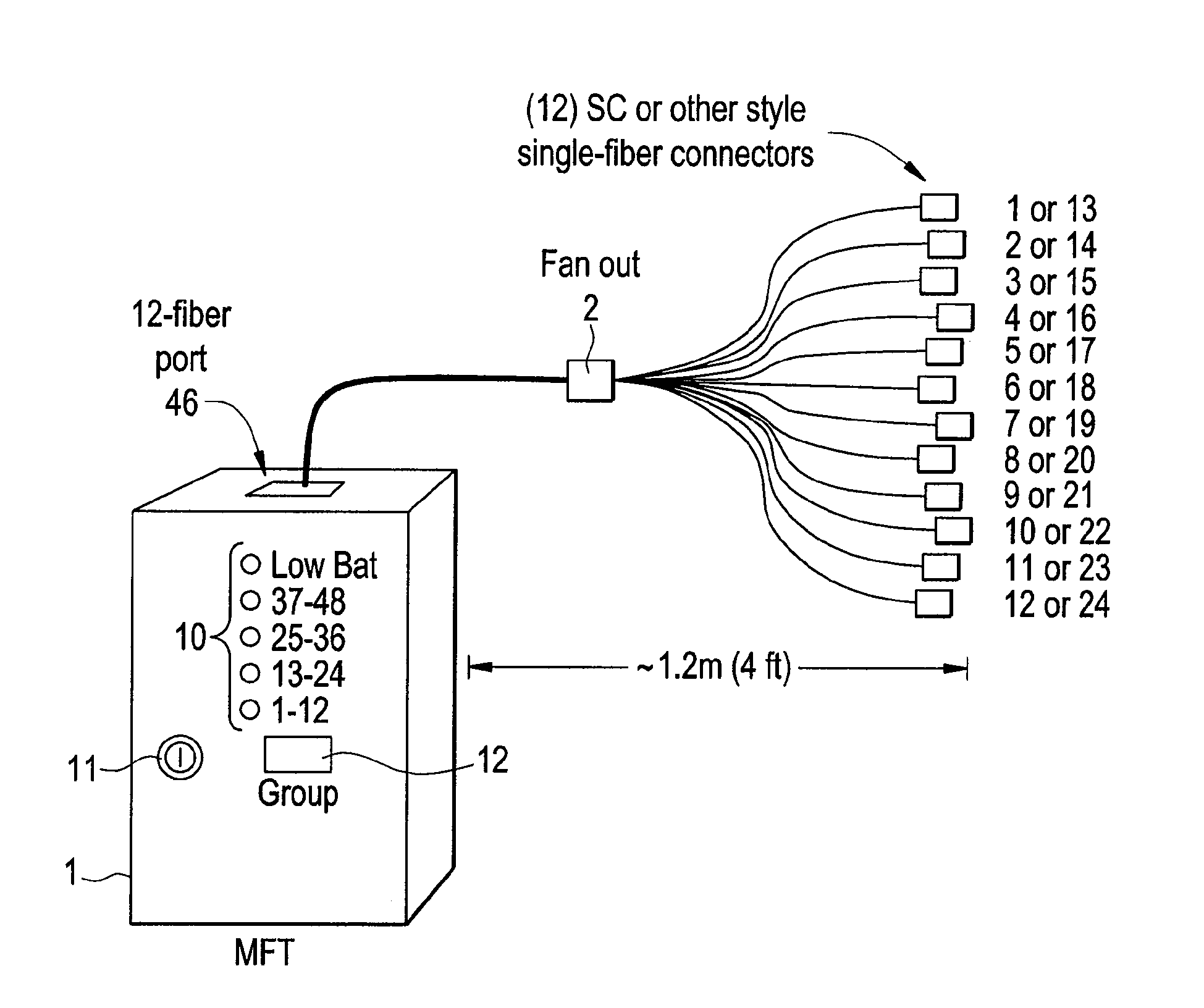
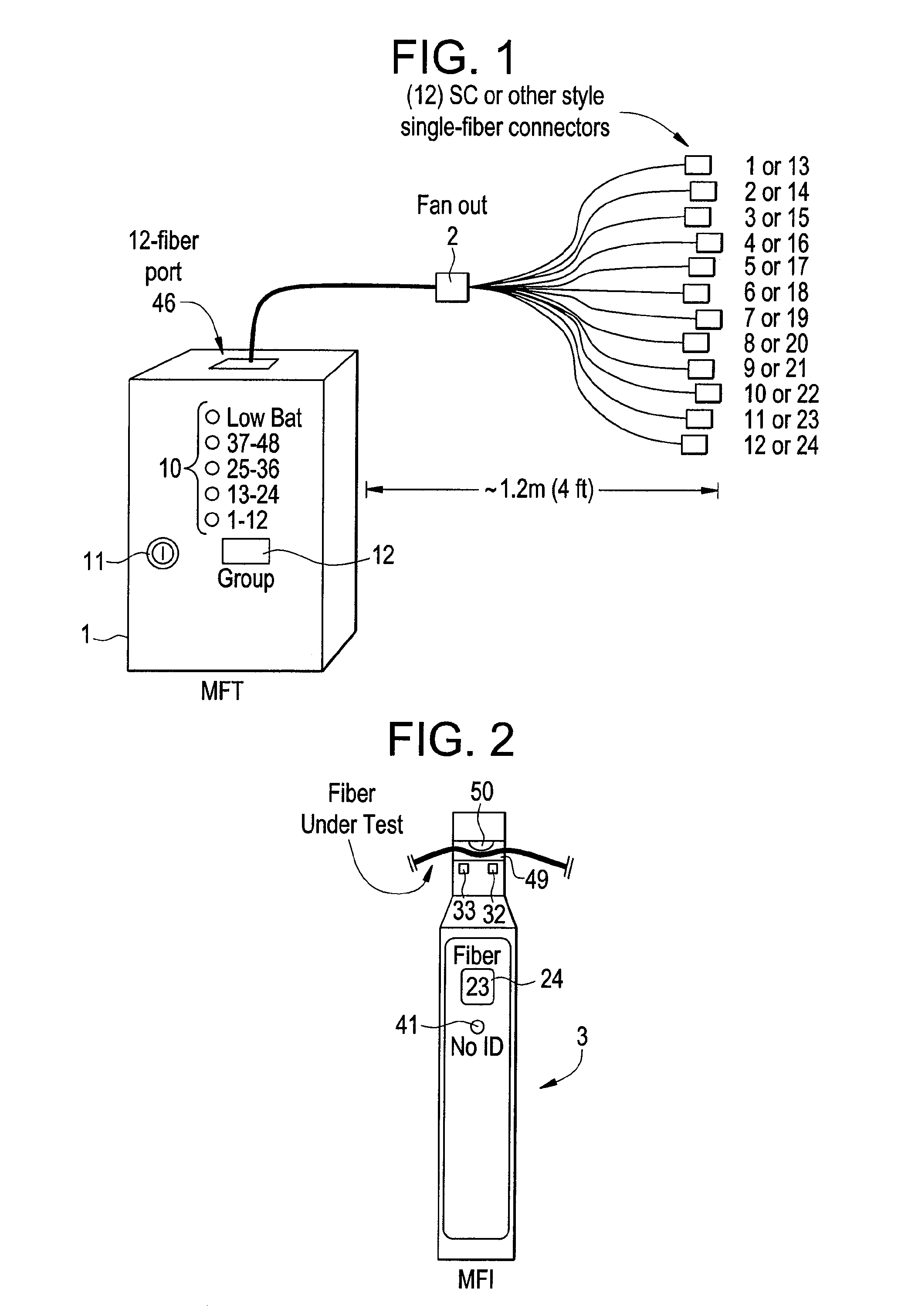
[0032]An exemplary Multifiber Tracer (MFT) 1 is a single port (MPO-type) twelve fiber output 1550 nm source. It is designed around twelve discrete laser sources (that can be, for example, 1550 nm single mode) tied into an MPO fan-out connector 2. The MFT 1 can be packaged, for example, in a Pactec LH45-100 style case. The MFT has a keypad. All calibration and operation can be performed via the keypad. Additionally, calibration can be controlled via an onboard USB port. The unit can be powered by 2 AA alkaline or NiMH batteries or an AC adapter.

[0033]The MFT 1 generates a digital code by using a unique data burst for each individual fiber, which is transmitted from the test port and is which is used to automatically identify the fiber under test. This feature is used in conjunction with a Multi-Fiber Identifier (MFI) 3 to provide automatic fiber identificati...


PUM


Abstract

A method of identifying or tracing one of a plurality of fiber optic fibers including transmitting a plurality of fiber identification data signals into ends of a plurality of fiber optic fibers, wherein a different data signal is transmitted to each of the plurality of fiber optic fibers; and identifying one of the plurality of fiber optic fibers based on the signal transmitted on the one fiber; wherein the data signals are digital codes.

Description

CROSS-REFERENCE TO RELATED APPLICATIONS[0001]This application claims priority from U.S. Provisional Application No. 60 / 942,569 filed on Jun. 7, 2007, the disclosure of which is incorporated herein by reference.BACKGROUND OF INVENTION[0002]1. Field of Invention[0003]Methods consistent with the present invention relate to a method of detecting and identifying fiber optic fibers and ribbons. More particularly, the present invention relates to a method of fiber optic ribbons by detecting a unique digital code in an optical fiber.[0004]2. Description of the Related Art[0005]Optical Fiber Identifiers or OFIs operate by bending a buffered or jacketed optical fiber and measuring any light that escapes as the result of the controlled bend. When used for fiber identification, traditional OFIs require that one end of the fiber to be identified be connected to a source that can generate an optical signal modulated at one of several frequencies, from about 270 Hz to 2 kHz, commonly used for fibe...

Claims


Application Information

Patent Timeline
IPC IPC(8): G01N21/00
CPCG01M11/332
Inventor GLINES, MICHAELFANG, JIANXUMBLAIR, CHRISTOPHER
Owner AFL COMM LLC
Why Eureka
Try Eureka