Parabola antenna

a technology of parabola and antenna, applied in the direction of antenna, antenna details, waveguide horns, etc., can solve the problems that the parabola may not be up to the standard, and achieve the effect of reducing the leakage of radio waves, reducing the propagation of radio waves, and simple configuration

Inactive Publication Date: 2010-09-30
NEC CORP
View PDF8 Cites 26 Cited by
  • Summary
  • Abstract
  • Description
  • Claims
  • Application Information

AI Technical Summary

Benefits of technology

[0012]According to the present invention, in the parabolic antenna, the choke groove is formed in at least one of the joint area between the reflecting mirror supporting member and the reflector and the joint area between the reflecting mirror suppo

Problems solved by technology

Due to the leakage of radio waves, if a radiation pattern standar

Method used


Image

  • Parabola antenna
  • Parabola antenna
  • Parabola antenna

Examples


first exemplary embodiment

[0036][First Exemplary Embodiment]

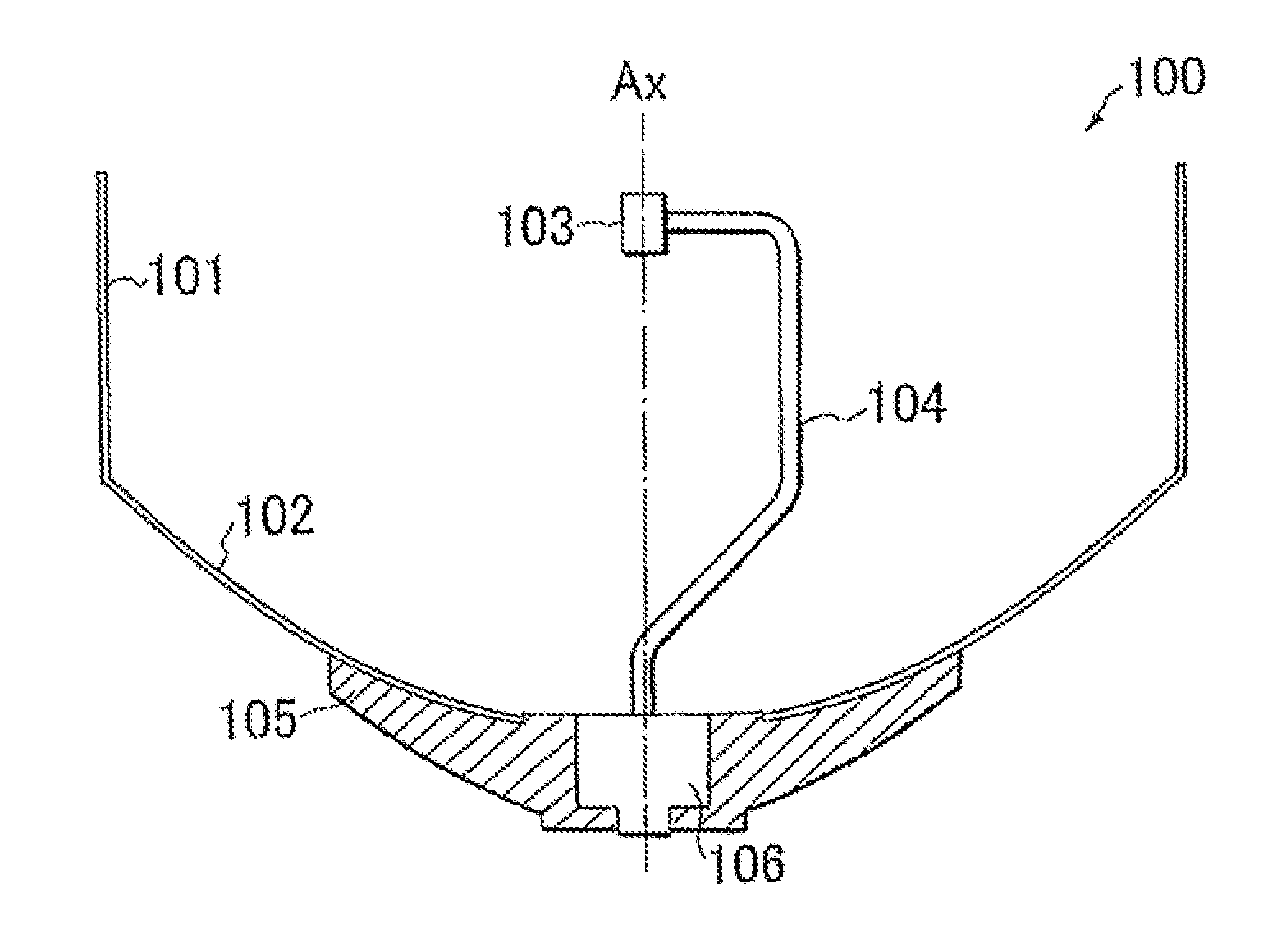
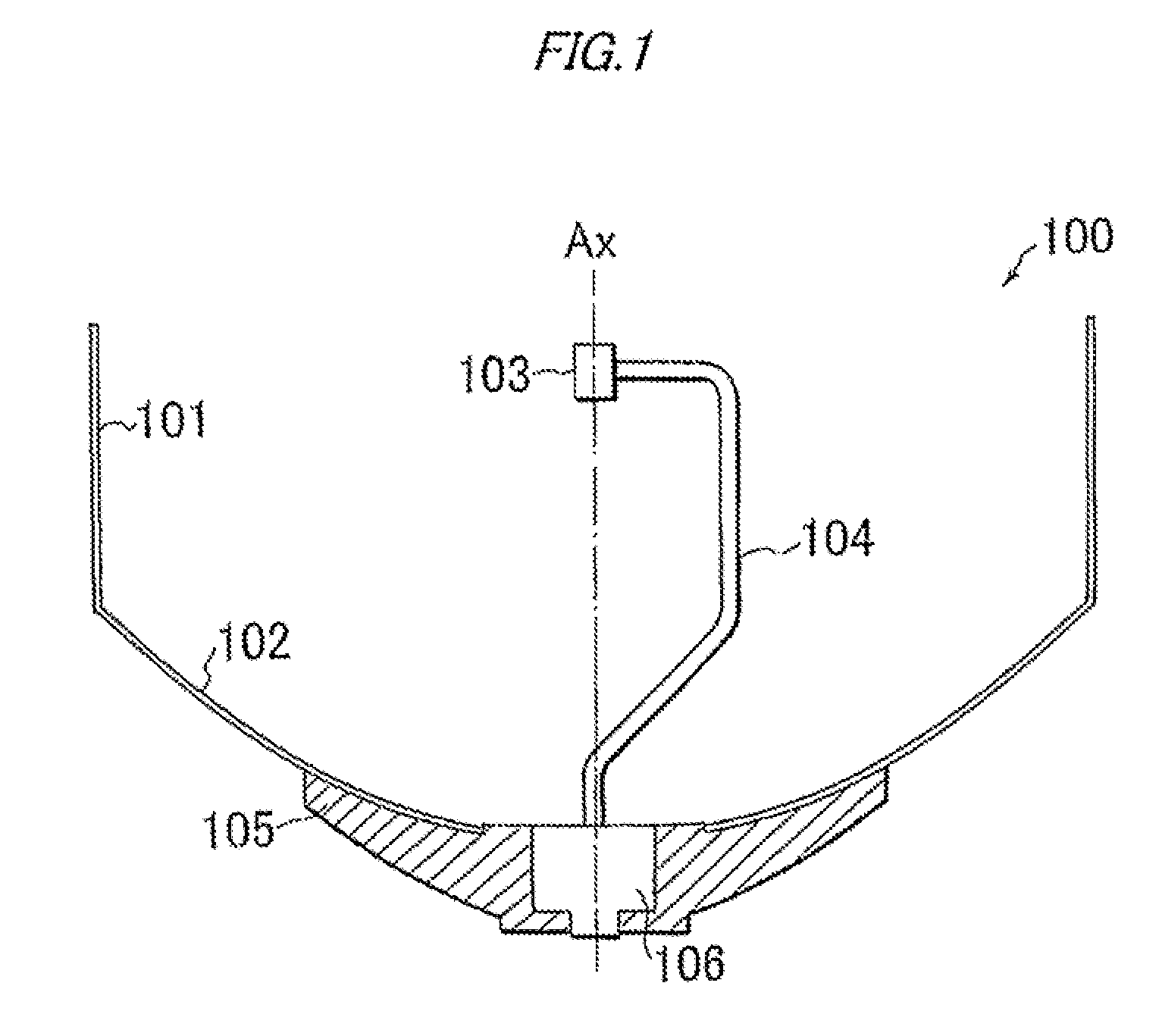
[0037]FIG. 1 is a cross-sectional view illustrating the basic configuration of a parabolic antenna according to a first exemplary embodiment of the present invention.

[0038]As shown in FIG. 1, the parabolic antenna 100 of the present exemplary embodiment is used, for example, as a transmitting / receiving antenna for a communication device (not shown). The basic configuration of the parabolic antenna 100 has a shroud 101, a reflector 102, a horn 103, a feed 104, a reflecting mirror supporting member (also referred to as “backup structure” or the like) 105, and a feed fitting adapter 106 (In FIG. 1, the choke grooves described below are omitted for reasons of explanation).

[0039]The shroud 101 is attached to the front side of the reflector 102, keeping radio waves from being radiated behind the parabolic antenna 100. The reflector 102 has a reflecting surface (parabolic mirror surface) on which a curve of rotational parabolic surface is formed. The refle...

second exemplary embodiment

[0068][Second Exemplary Embodiment]

[0069]FIG. 14 is a cross-sectional view detailing the configuration of a parabolic antenna according to a second exemplary embodiment of the present invention.

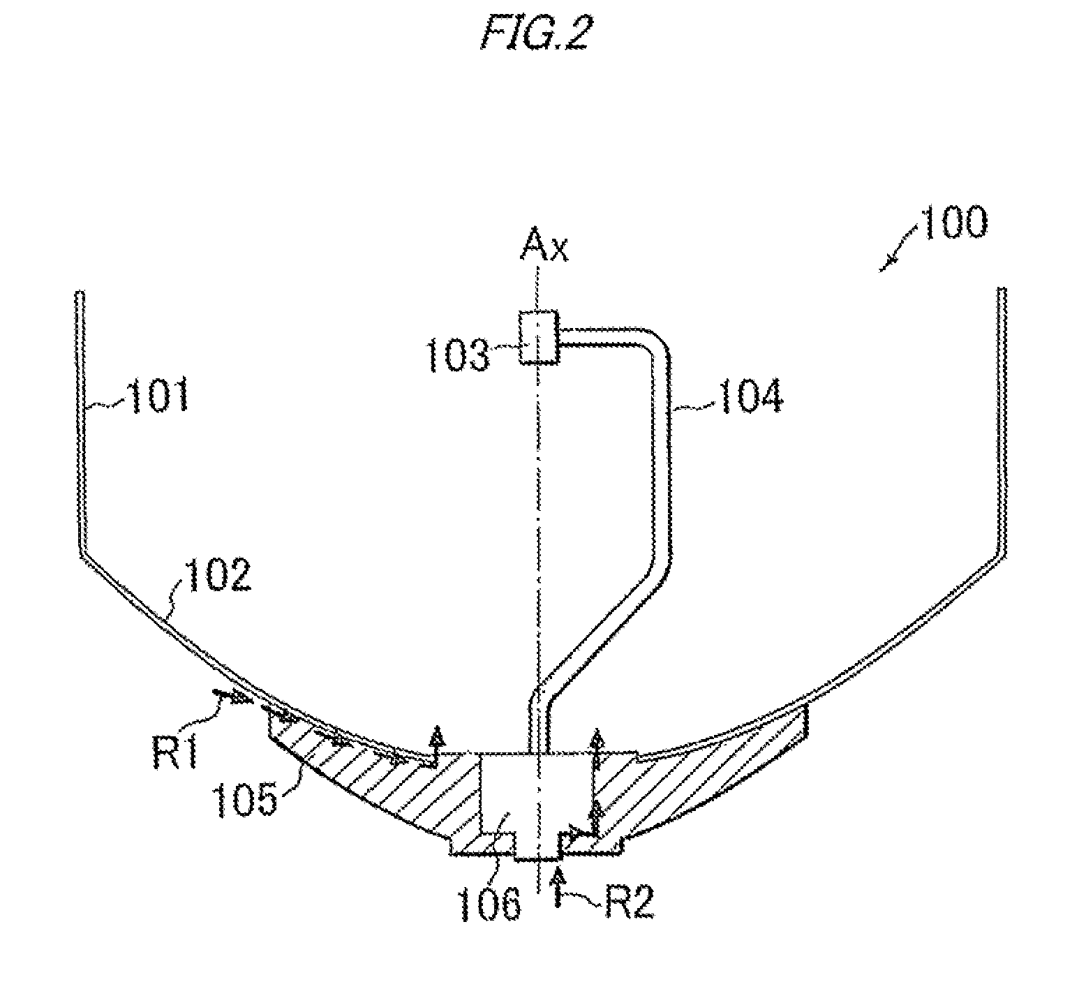
[0070]As shown in FIG. 14, according to the present exemplary embodiment, like the first exemplary embodiment, the configuration of the parabolic antenna 100 has the shroud 101, the reflector 102, the horn 103, the feed 104, the reflecting mirror supporting member 105, and the feed fitting adapter 106. However, the way the choke grooves 107 for the radio wave leakage route R2 are formed is different. That is, as shown in FIG. 14, the choke grooves 107 for the radio wave leakage route R1 are formed, like those in the first exemplary embodiment, in the joint area between the reflecting mirror supporting member 105 and the reflector 102 on the side of the reflecting mirror supporting member 105. On the other hand, the choke grooves 107 for the radio wave leakage route R2 are formed in the joint ...


PUM


Abstract

Provided is a parabolic antenna that suppresses leakage of radio waves with a simpler configuration. The parabolic antenna includes a horn that transmits and receives signals; a feed that supports the horn and relays the signals the horn transmits and receives; a reflector that reflects the received signals to focus the received signals on the horn and reflects the signals from the horn to transmit the signals; a reflecting mirror supporting member that supports the reflector; and a feed fitting adapter that enables the feed to be fitted into the reflecting mirror supporting member. A choke groove is formed in at least one of a joint area between the reflecting mirror supporting member and the reflector and a joint area between the reflecting mirror supporting member and the feed fitting adapter, which suppresses propagation of radio waves traveling through the gap of the joint area.

Description

TECHNICAL FIELD[0001]The present invention relates to a parabolic antenna and particularly to a parabolic antenna for reducing leakage of radio waves.BACKGROUND ART[0002]In a conventional assembled parabolic antenna, radio waves may leak from gaps between the surface of a reflecting mirror, a supporting member of the reflecting mirror, and a feed fitting adapter, which are components of the parabolic antenna. Due to the leakage of radio waves, if a radiation pattern standard is strict, the parabolic antenna may not be up to the standard.[0003]Regarding the above matter, PTL 1 disclose a technique of reducing leakage of radio waves using a choke element that is formed by one portion of a case with one or more concave sections provided in the direction from a transmitting antenna to a receiving antenna.[0004]Citation List[0005]Patent Literature[0006]PTL 1 JP-A-2005-91238SUMMARY OF INVENTION Technical Problem[0007]If the reflecting mirror surface and the reflecting mirror supporting me...

Claims


Application Information

Patent Timeline
IPC IPC(8): H01Q13/02H01Q1/00H01Q1/24
CPCH01Q19/021H01Q19/134H01Q19/13
Inventor OMURO, NORIHIKOOGUMA, NOBUHIKO
Owner NEC CORP
Why Eureka
Try Eureka