Buffer and liquid ejecting apparatus

a liquid ejecting apparatus and buffer technology, applied in mechanical apparatus, check valves, functional valve types, etc., can solve the problem of temporarily unstable liquid supply for liquid ejecting, and achieve the effect of stable liquid supply

Inactive Publication Date: 2010-09-30
SEIKO EPSON CORP
View PDF4 Cites 4 Cited by
  • Summary
  • Abstract
  • Description
  • Claims
  • Application Information

AI Technical Summary

Benefits of technology

[0011]An advantage of some aspects of the invention is to provide a buffer and a liquid ejecting apparatus in which it is possible to maintain the stable supply of liquid for a liquid ejecting head.

Problems solved by technology

As a result, when liquid has begun to be supplied from the liquid chamber expanded into the dome shape, there is a risk that the supply of liquid for the liquid ejecting is temporarily unstable.

Method used


Image

  • Buffer and liquid ejecting apparatus
  • Buffer and liquid ejecting apparatus
  • Buffer and liquid ejecting apparatus

Examples


Embodiment Construction

[0045]Embodiments of a buffer and a liquid ejecting apparatus of the invention will be described below with reference to FIGS. 1 to 9C. In figures used for the following explanation, the size of each member is appropriately changed in order to illustrate each member to be recognized.

[0046]In addition, in the embodiments, an ink jet printer (hereinafter referred to as a “printer”) in which ink (liquid) is ejected to be placed on paper or other recording media to record characters, images or the like will be described as an example of a liquid ejecting apparatus.

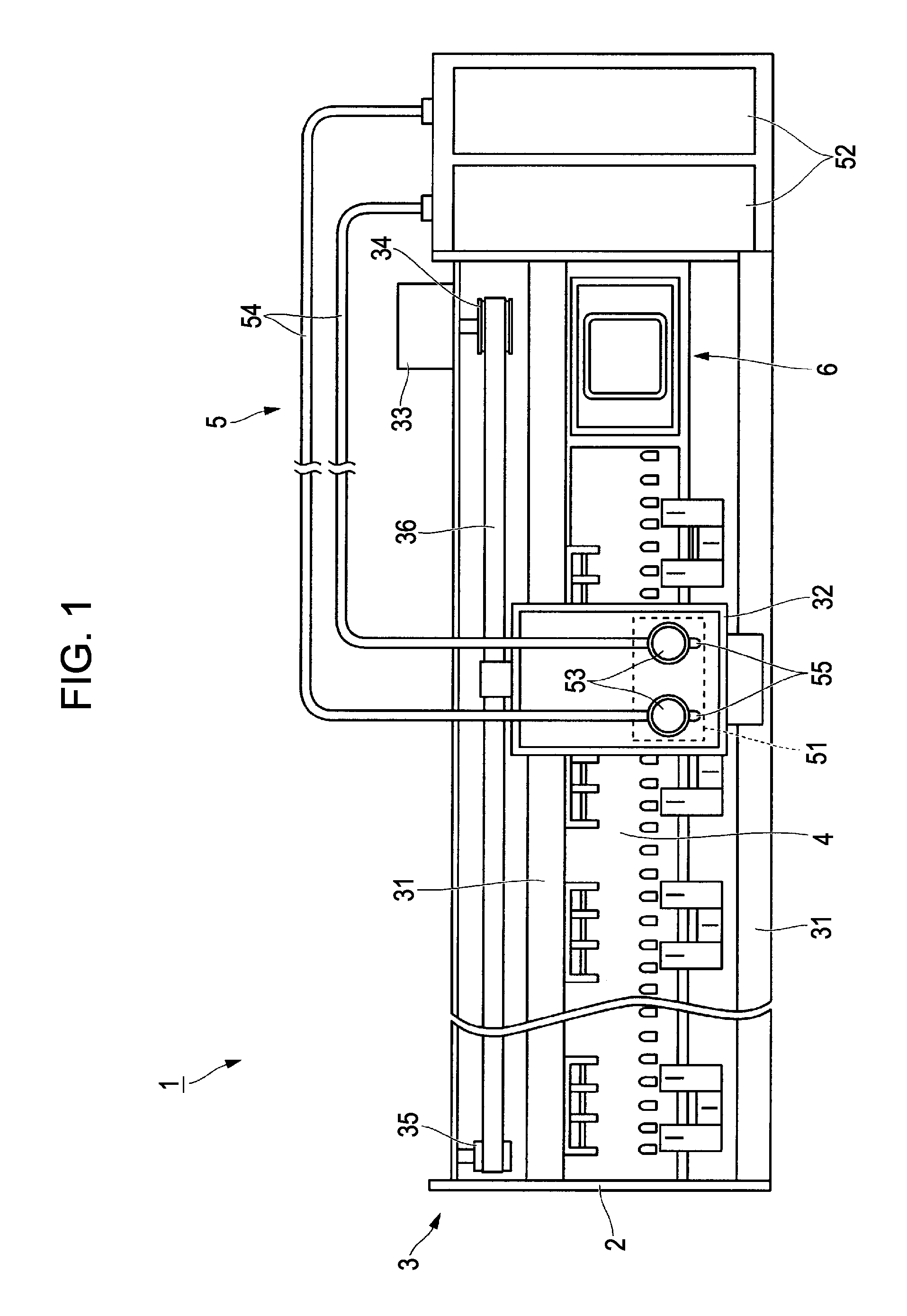
[0047]FIG. 1 is a diagram illustrating the configuration of a printer 1 according to the embodiment.

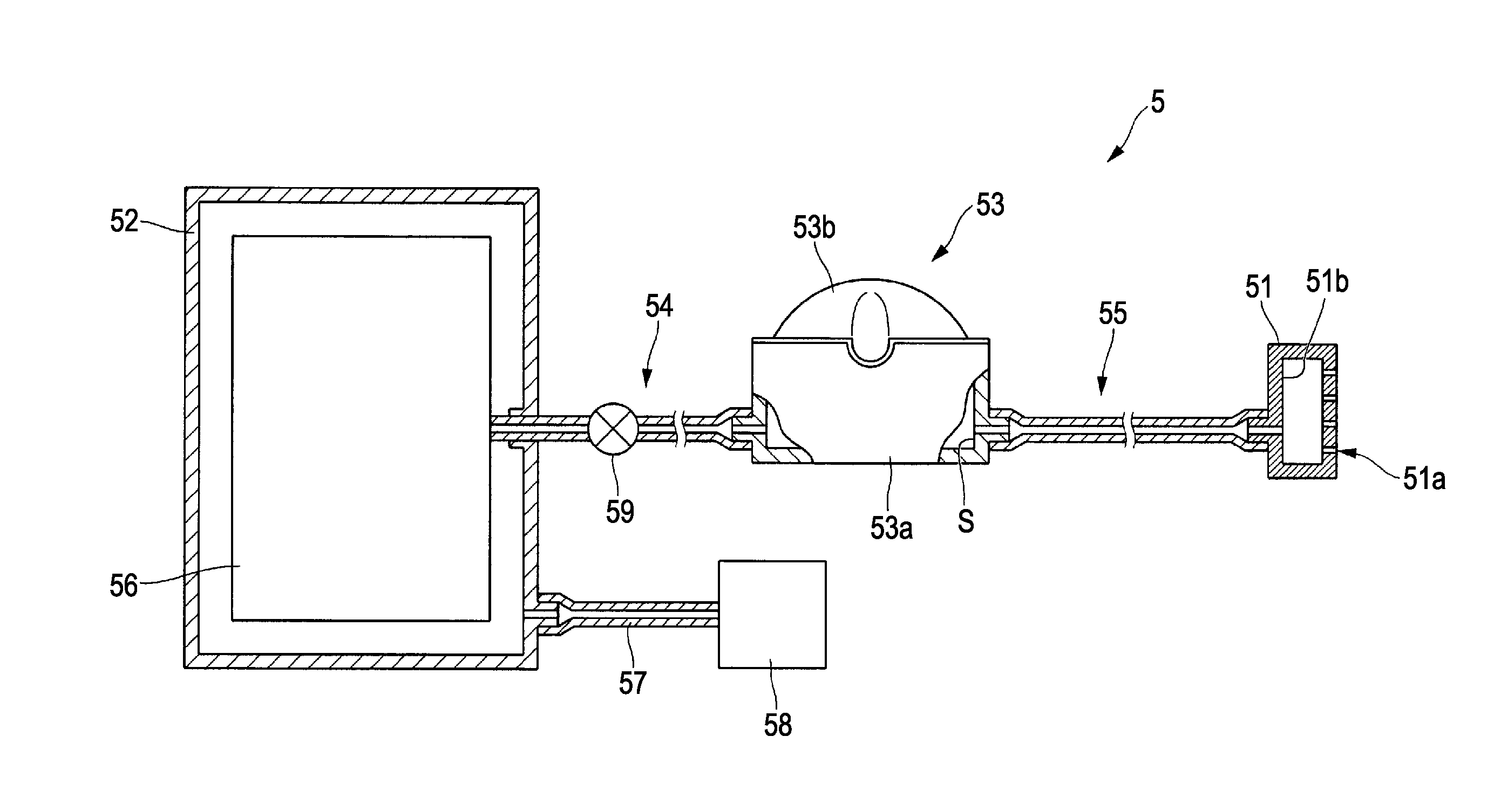
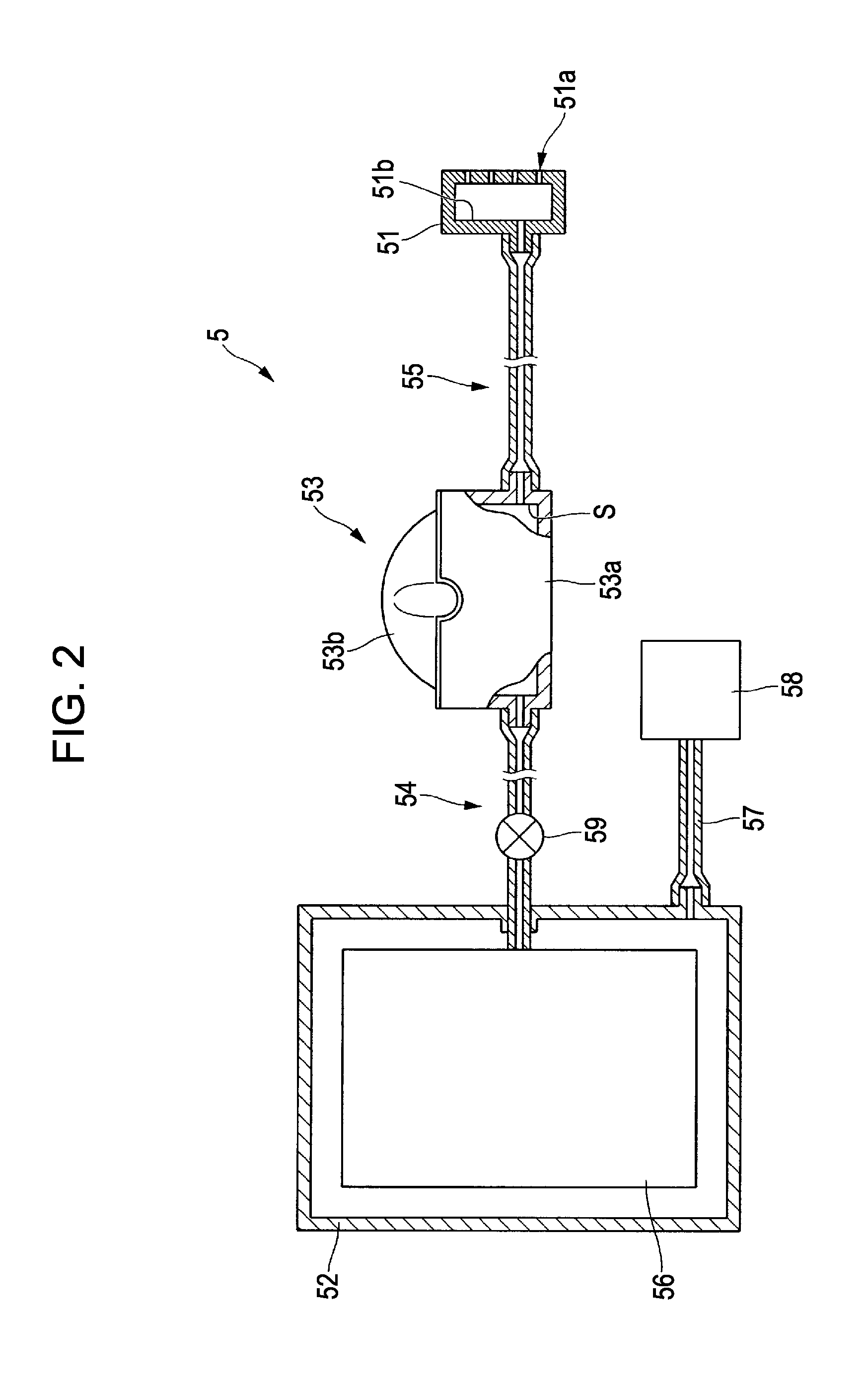
[0048]In the printer (liquid ejecting apparatus) 1, ink (liquid) is ejected to be placed on paper or other recording media to record characters, images or the like. The printer 1 includes a printer body 2, a carriage drive system 3, a platen 4, an ink supply system 5, and a capping unit 6.

[0049]The printer body 2 extends in a ho...


PUM


Abstract

A buffer receiving and supplying liquid includes: a cylindrical cup having a bottom; and a flexible film forming a sealed space between the cup and the film, wherein one of a depressed portion and a projecting portion is formed at an open end of the cup, and wherein the film is attached to the open end and one of the depressed portion and the projecting portion along the surface thereof.

Description

[0001]This application claims the benefit of Japanese Patent Application No. 2009-076321, filed Mar. 26, 2009, which is expressly incorporated herein by reference in its entirety.BACKGROUND[0002]1. Technical Field[0003]The present invention relates to a buffer and a liquid ejecting apparatus.[0004]2. Related Art[0005]A liquid ejecting apparatus which ejects liquid such as ink from a liquid ejecting head and places a liquid droplet on a recording medium to record characters, images or the like has been known in the past.[0006]As shown in JP-A-2007-21996, a liquid ejecting apparatus is provided with a buffer receiving a certain amount of liquid in order to maintain the stable supply of liquid to a liquid ejecting head.[0007]The buffer disclosed in JP-A-2007-21996 is disposed on a side of the liquid ejecting head, the side being opposite to a side where a nozzle is provided. The buffer has a flexible film. A sealed liquid chamber is formed between the film and the liquid ejecting head....

Claims


Application Information

Patent Timeline
Patent Type & Authority Applications(United States)
IPC IPC(8): B41J2/175F16K21/00
CPCB41J2/175B41J2/18B41J2/17596
Inventor ONO, HIROKAZU
Owner SEIKO EPSON CORP
Why Eureka
Try Eureka