Spring-loaded driving member for timepiece movement

a technology of timepiece movement and driving member, which is applied in the direction of clock driving mechanism, instruments, electromechanical clocks, etc., can solve the problems of large thickness of watch movement, large space requirement of driving arrangement in axial direction, and the inability to increase the expansion turn of a barrel spring without reducing its efficiency, so as to save energy and reduce height , the effect of simple construction

Active Publication Date: 2010-09-30
MONTRES JAQUET DROZ SAMONTRES JAQUET DROZ AGMONTRES JAQUET DROZ LTD
View PDF10 Cites 15 Cited by
  • Summary
  • Abstract
  • Description
  • Claims
  • Application Information

AI Technical Summary

Benefits of technology

[0004]The present invention relates to a driving member with two coaxial superposed barrels that is improved so that it can store more energy than a classic member of this type of the same height, or it can have a reduced height using the same springs for the same energy storage capacity. An additional aim is to achieve this with a simple construction, easy assembly and with a small number of parts.
[0006]Therefore, the essential improvement achieved by the invention lies in the possibility of omitting the two covers arranged to face one another and separated by a gap, as seen in particular in the above-mentioned patents EP 1 115 040 and EP 1 657 604. These omitted elements are preferably replaced by a simple separation washer, the purpose of which in particular is to prevent the turns of the two springs from crossing one another when the springs are relaxed. This washer can be very thin and formed from a sheet of an antifriction material such as PTFE, for example. The two springs can thus be brought as close as possible to one another axially and the housings of the barrels can be provided with a height that is close to that of the springs. The washer of antifriction material can advantageously extend between the respective cylindrical parts of the housings that can thus be brought as close to one another as possible. These arrangements both allow the total height of the driving member to be reduced while retaining the dimensions of the springs according to the prior art and the height of the springs, and therefore the amount of energy and the power reserve, to be increased with the same total volume of the driving member. Moreover, the number of parts of the device is reduced by one or more units in relation to the designs according to the prior art.

Problems solved by technology

However, the coaxial and superposed arrangement of the usual barrels, as may be seen in the abovementioned patents, results in the driving arrangement having a relatively large space requirement in axial direction, i.e. in the direction perpendicular to the main bottom plate of the timepiece movement.
Consequently, the total height of an arrangement with superposed barrels always gives rise to a relatively large thickness of the watch movement and this constitutes a disadvantage in most cases.
Since the number of expansion turns of a barrel spring cannot be increased without reducing its efficiency, if the manufacturer wishes to reduce the height of the barrels and therefore of the springs, he automatically reduces the energy that can be stored and thus also the power reserve of the watch.

Method used


Image

  • Spring-loaded driving member for timepiece movement
  • Spring-loaded driving member for timepiece movement

Examples


Embodiment Construction

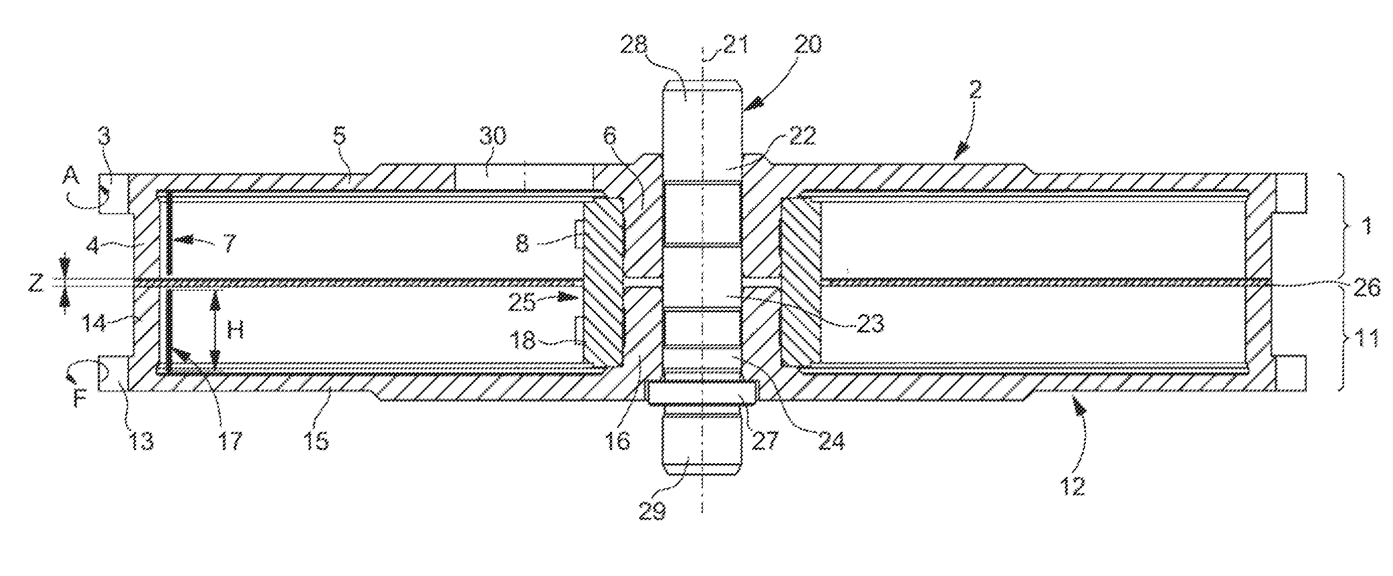
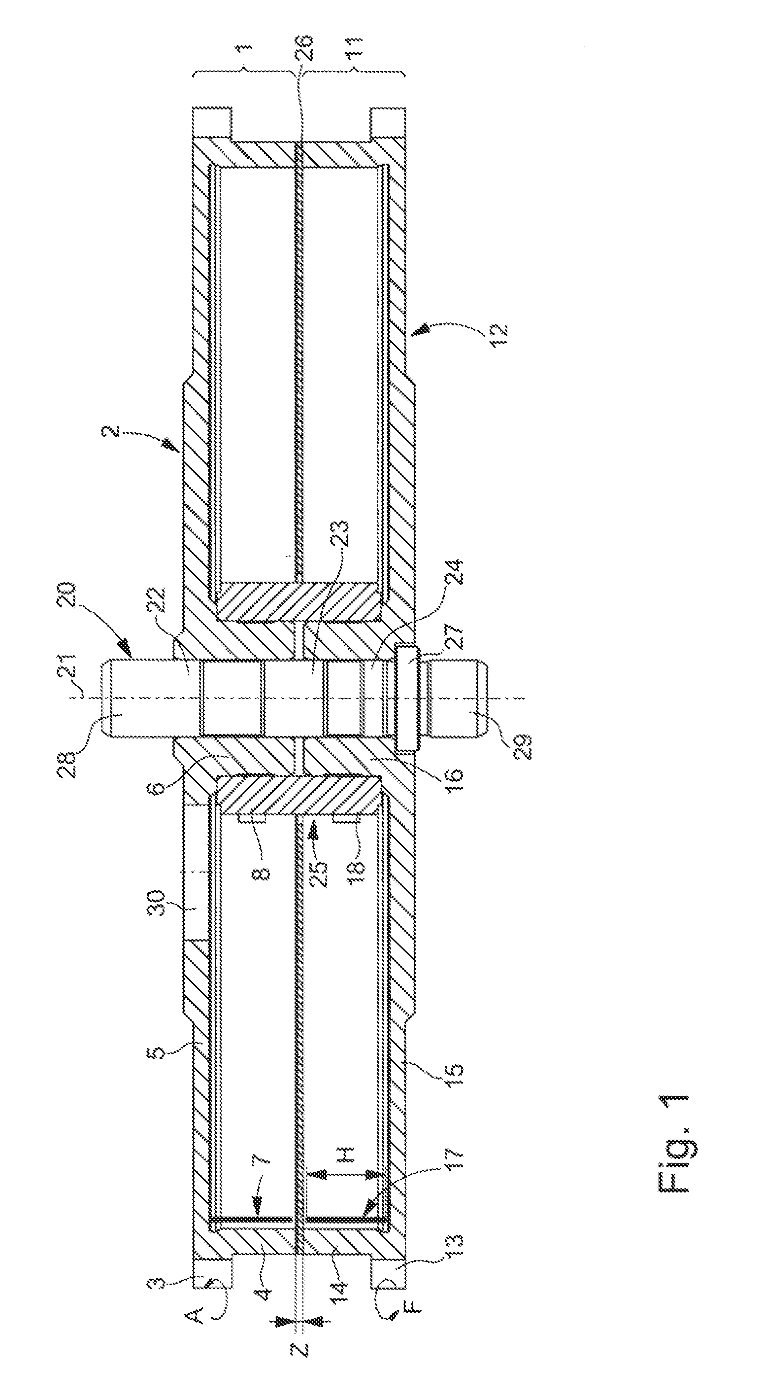
[0011]The driving member shown in the drawing comprises a first barrel 1 and a second barrel 11, which are superposed and mounted on a common shaft 20 to rotate independently of one another around the axis 21 of the shaft. The first barrel 1 has a cylindrical housing 2 having an outer tooth arrangement 3, a cylindrical outer drum 4, a base 5 and a wide cylindrical central hub 6 rotatably mounted on bearing surfaces 22 and 23 of the shaft 20. The housing 2 contains a driving spring 7 rolled up in a spiral, of which only a single turn is shown for clarity of the drawing. The outer end of the spring 7 is coupled to the drum 4 by a slip spring device, while its inner end is fastened to a core 8 mounted to be rotatable around the hub 6.

[0012]The structure of the second barrel 11 is the same as that of the first, having a housing 12 with a tooth arrangement 13, a drum 14, a base 15 and a hub 16 rotatably mounted on bearing surfaces 23 and 24 of the common shaft 20. The bearing surfaces 22...


PUM


Abstract

The invention relates to a driving member for a timepiece movement, that comprises two superimposed coaxial barrels (1, 11) coupled in series, each barrel including a spring provided in a cylindrical housing rotatingly mounted on a common shaft (20). The respective housings (2, 12) of the barrels are positioned opposite each other and do not include a lid, said springs (7, 17) being separated only by a separation washer (26) or a gap. Preferably, the separation washer (26) is made of a sheet of an anti-friction material and extends between the respective outer drums (4, 14) of the barrel housings. This arrangement can be used for increasing the height (H) of the springs, and thereby the amount of energy and the power reserve of the watch for an identical global volume of the driving member, or for reducing the total height of the driving member. The number of parts is also reduced and the mounting is made easier. Such a driving member is particularly intended for watches with a high power reserve.

Description

BACKGROUND OF THE INVENTION[0001]The present invention relates to a spring-loaded driving member for a timepiece movement comprising two coaxial barrels coupled in series, each barrel having a rotatable cylindrical housing provided with an outer tooth arrangement and a base, and a spring rolled up inside the housing and having an outer end coupled to the housing and an inner end coupled to a core, wherein the respective cores of the barrels are interdependently rotatable and the respective bases of the barrels are located axially opposite one another. In other words, the two barrels are superposed and face one another, an arrangement that is represented in particular in patent applications EP 1 115 040 (with two groups of two barrels) and EP 1 657 604.[0002]In the field of mechanical watch movements it is well known to replace the usual driving member comprising a single barrel fitted with a spring by a group of two barrels coupled in series in order to store a sufficiently large am...

Claims


Application Information

Patent Timeline
Patent Type & Authority Applications(United States)
IPC IPC(8): G04B1/16
CPCG04B1/12
Inventor MERTENAT, OLIVIER
Owner MONTRES JAQUET DROZ SAMONTRES JAQUET DROZ AGMONTRES JAQUET DROZ LTD
Why Eureka
Try Eureka