Multi-Point to Multi-Point Intercom System

Active Publication Date: 2010-09-30
CLEAR COM
View PDF12 Cites 48 Cited by
  • Summary
  • Abstract
  • Description
  • Claims
  • Application Information

AI Technical Summary

Problems solved by technology

For an intercom system for which each endpoint have the flexibility to decide who they are listening or talking to, the mixing is very computing intensive as each channel will have completely different listening experience.
A side effect of mixing is the addition of extra propagation delay.
Moreover, mixing can only be done using linear non encoded signals, meaning that all signals must be decoded before being mixed and then re-enc

Method used


Image

  • Multi-Point to Multi-Point Intercom System
  • Multi-Point to Multi-Point Intercom System
  • Multi-Point to Multi-Point Intercom System

Examples


Embodiment Construction

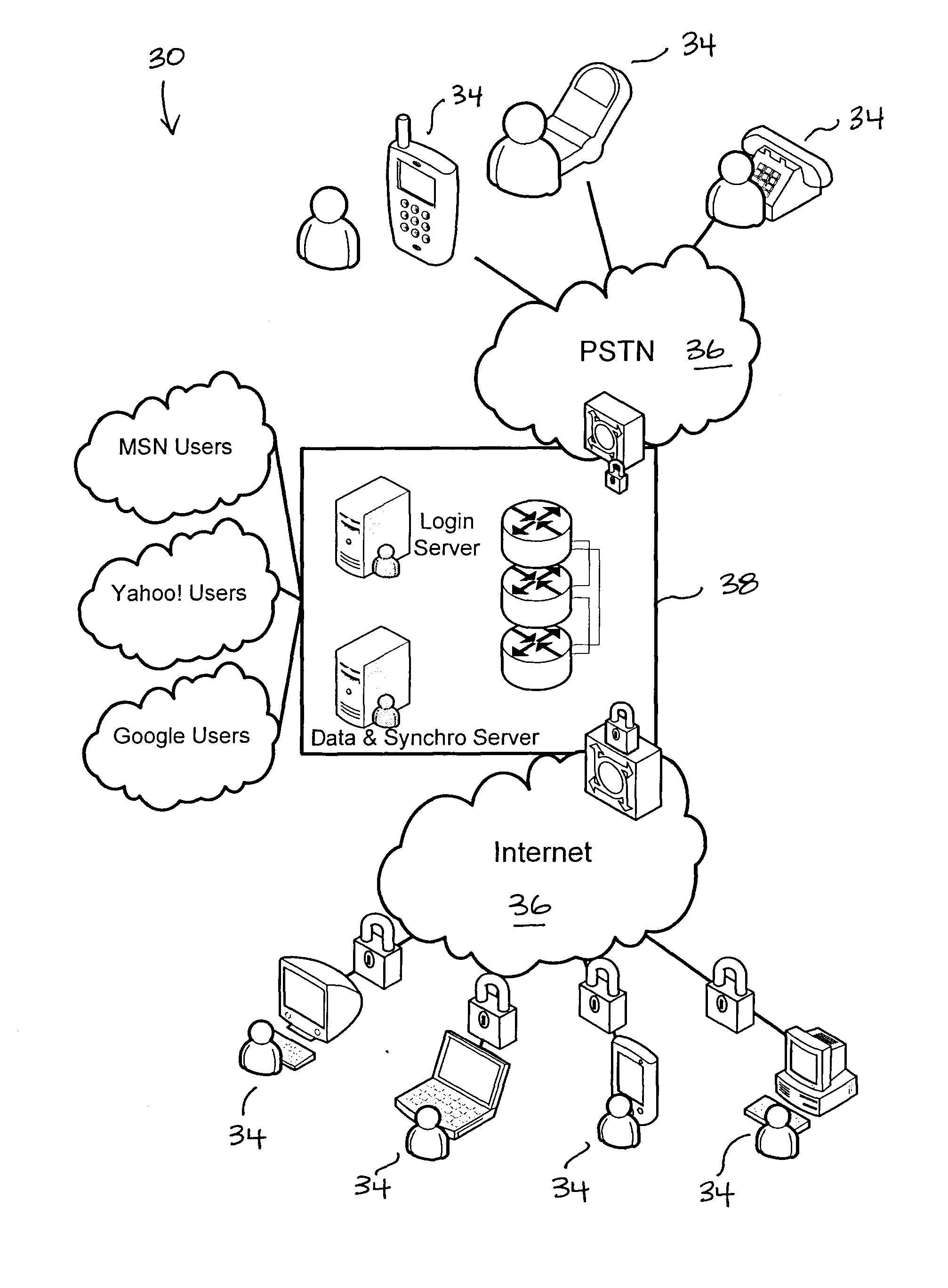
[0112]In the following description, similar features in the drawings have been given similar reference numerals. To preserve the clarity of the drawings, some references numerals have been omitted, if they were already identified in a preceding figure.

[0113]In the context of the present description, the expressions “conferencing” and “intercom system” include all types of communications or exchanges of information between a plurality of parties. Although the present invention was primarily designed for a global real-time conferencing and intercom technology over packet networks, it may be used for other kinds of applications, as apparent to a person skilled in the art. For this reason, the expression “global”, “real-time” or “packets” should not be taken as to limit the scope of the present invention and includes all other kinds of applications or items with which the present invention may be used and could be useful.

[0114]Moreover, in the context of the present description, the exp...


PUM


Abstract

A multi-point to multi-point intercom system, formed by at least one intercom server and a plurality of intercom terminals, the intercom terminals registered as talking or listening intercom terminals in an intercom session table. The intercom server sends to listening intercom terminals some or all of the unmixed audio packets received by talking intercom terminals according to the intensity signal value found in the header of the unmixed audio packets.

Description

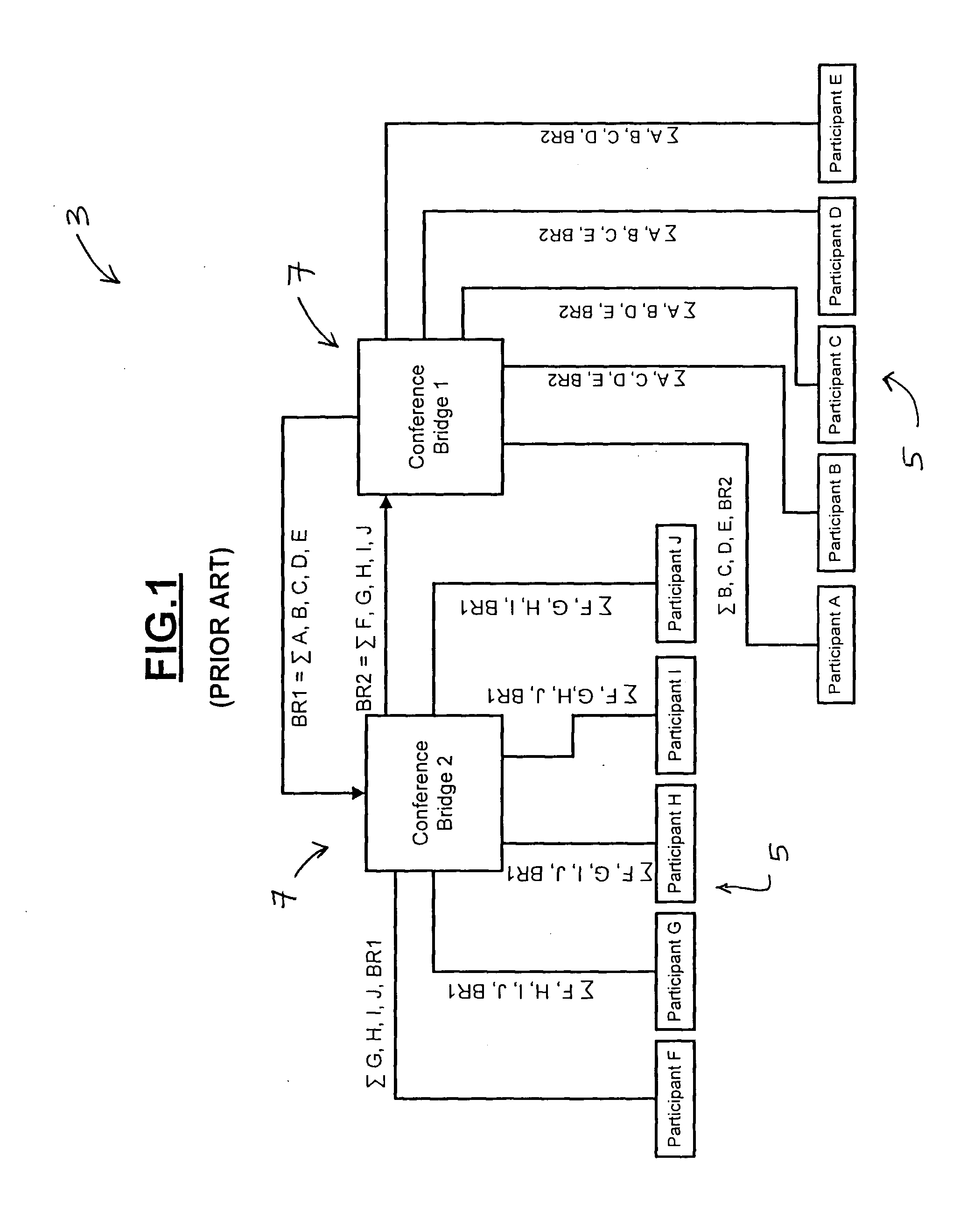
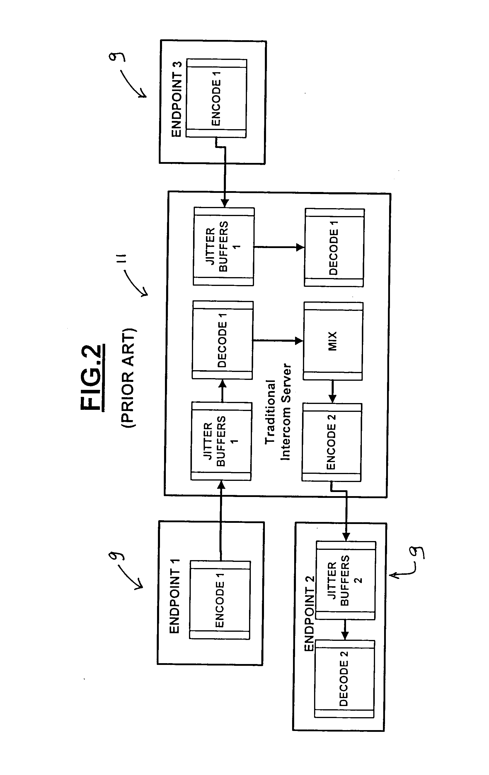
FIELD OF THE INVENTION[0001]The present invention relates to intercom systems and more particularly concerns an intercom system formed by at least one intercom server and a plurality of intercom terminals for allowing intercom terminals to exchange unmixed audio packets over a packet network, each of the unmixed audio packet having audio data and a header, the header having an intercom terminal identifier and an intensity signal value representative of the audio data.BACKGROUND OF THE INVENTION[0002]In prior art intercom or conferencing systems, audio signals travelling between each endpoint and the intercom server are represented as channels. Each endpoint traditionally carries one channel of audio to the server as well as receives one channel of audio from the server.[0003]Channelizing audio in a conferencing system causes the need to mix all active participants of the conference before transmitting the audio to each endpoint. For an intercom system for which each endpoint have th...

Claims


Application Information

Patent Timeline
IPC IPC(8): H04M1/00
CPCH04L63/0428H04L63/08H04L65/605H04M3/56H04L12/1822H04L63/166H04L65/765
Inventor MENARD, STEPHANEPAULER, ULRICHLAMOTHE, MARTINEMERSON, CLIFFROLET, BARTHELEMY
Owner CLEAR COM
Why Eureka
Try Eureka