Intercom system

a technology of intercom system and directory, applied in the field of intercom system, can solve the problems of inability to cater for complex door or gate release operations, difficulty in keeping this directory up to date, and damage to keypads

Inactive Publication Date: 2011-01-13
SWITCH AUTOMATION
View PDF3 Cites 45 Cited by
  • Summary
  • Abstract
  • Description
  • Claims
  • Application Information

AI Technical Summary

Problems solved by technology

A disadvantage is that with communication via the keypad only, the visitor must know the number for the required residence or premises.
Keeping this directory up to date can be challenging when residents or premises change hand frequently.
Keypads are also prone to damage from exposure to the elements and vandalism.
They are also unable to cater for complex door or gate release operations as is often required whereby a visitor may only gain access to the gates, doors, elevators, floors that the specific residence can allow.

Method used


Image

  • Intercom system
  • Intercom system
  • Intercom system

Examples


Embodiment Construction

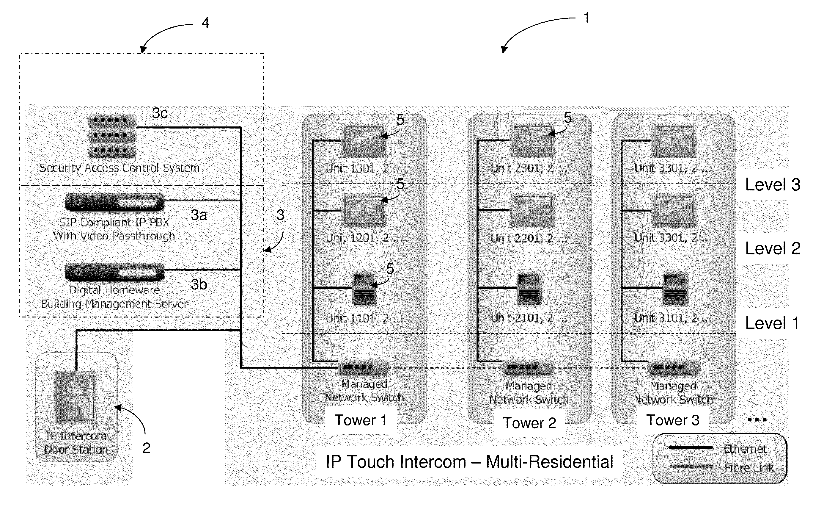
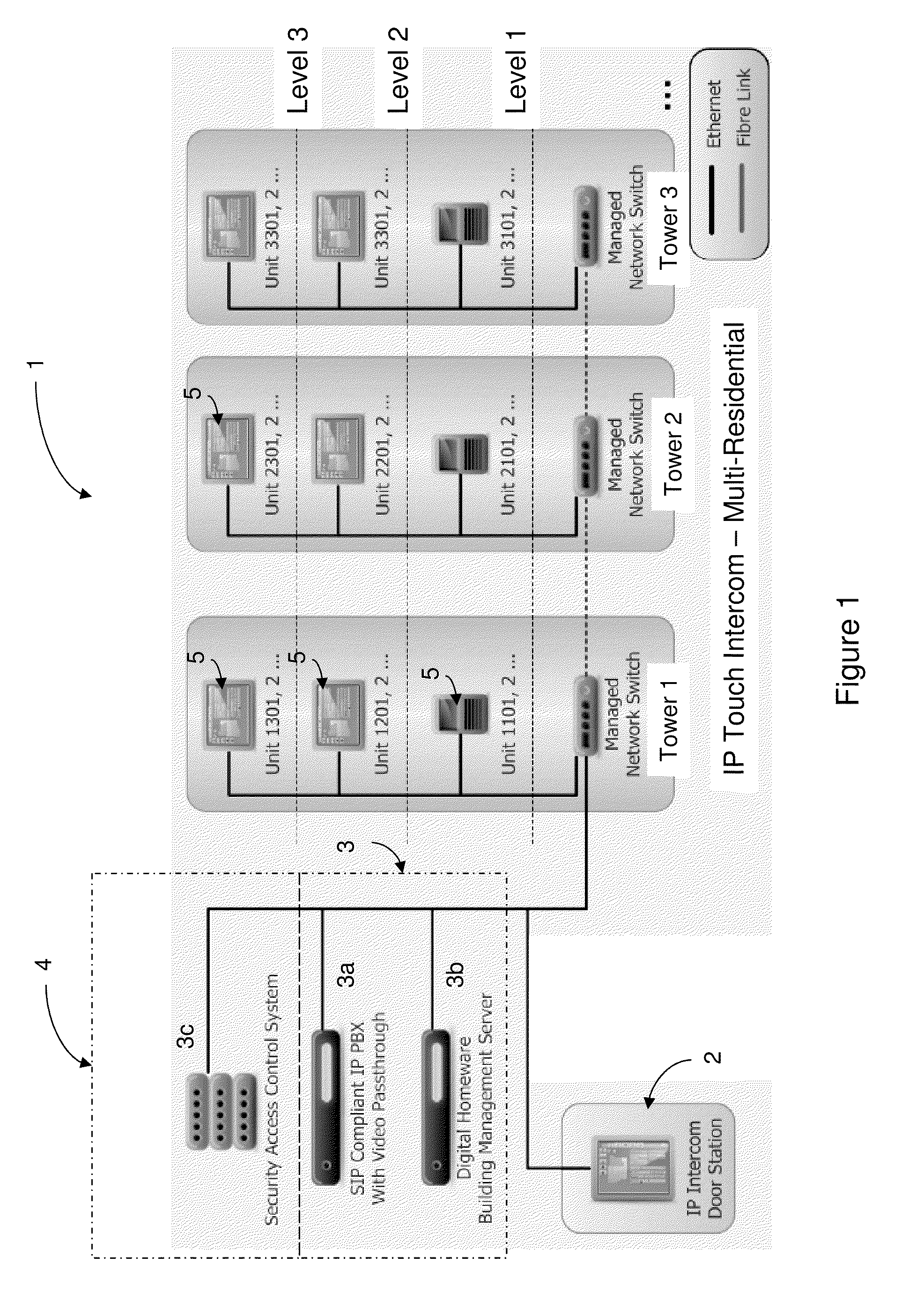
[0021]Referring to FIG. 1, there is shown an intercom system 1. The intercom system 1 comprises an entry station 2 in the form of a touch-screen user interface; a communications system 3; a security access control system 4; and a plurality of residence terminals 5 (in a variety of form factors). In the embodiment described herein, the various modules referred to above are coupled to one another via an Internet Protocol (IP) network and Voice over Internet Protocol (VOIP) is utilised to facilitate the handling of calls.

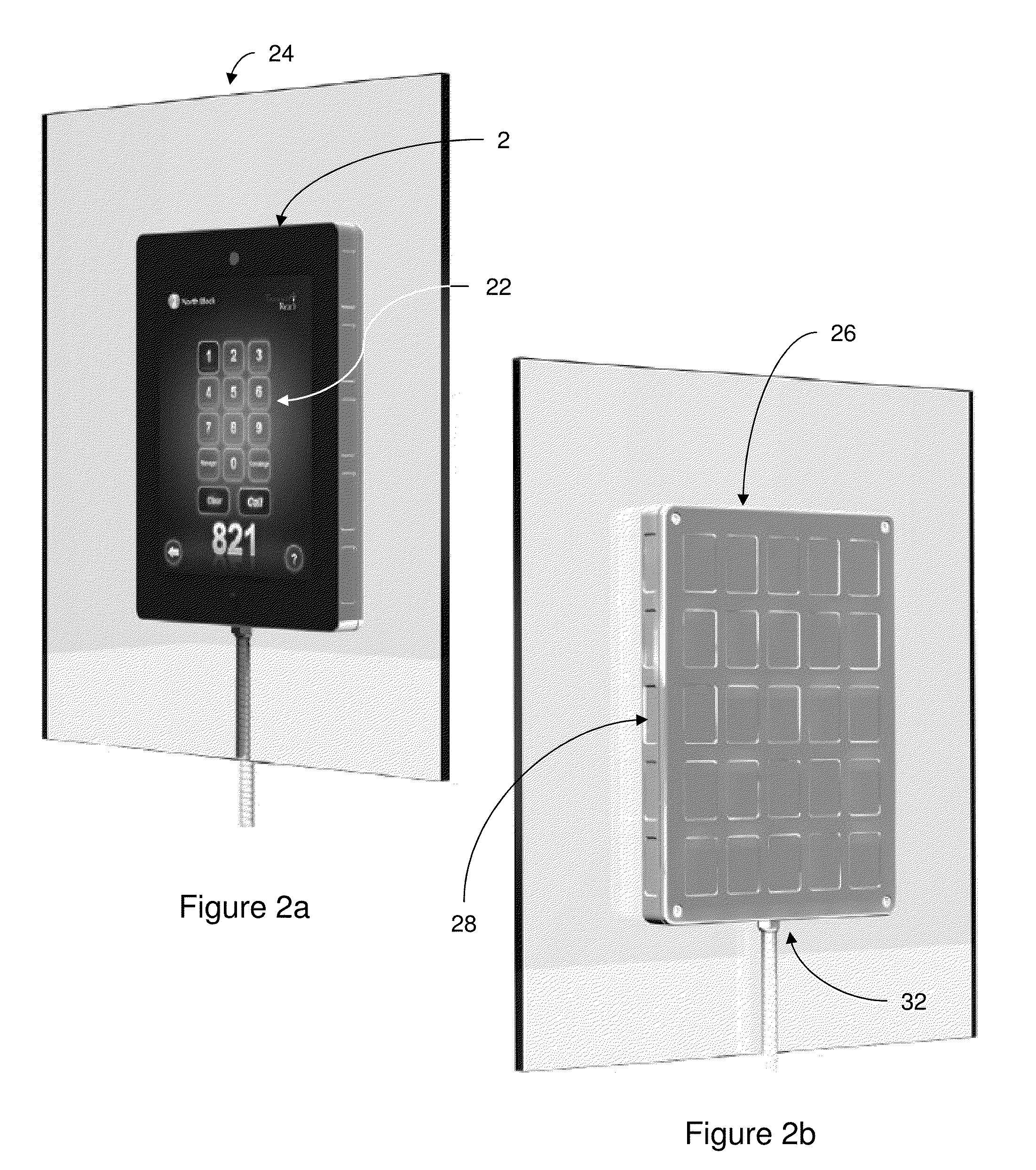
[0022]In more detail, and with additional reference to FIG. 2a, the entry station 2 is in the form of a touch-screen user interface. In accordance with the illustrated embodiment, the touch-screen interface 2 (hereafter “interface”) comprises a projective capacitive touch screen 22.

[0023]As persons skilled in the art will appreciate, projective capacitive screens include an array of sensing wires embedded within layers of a non-metallic material. When a conducting medi...


PUM


Abstract

An entry station for an intercom system comprises a touch-screen user interface operable to facilitate a dialling function. A communications module is provided which is arranged to communicate with at least one destination terminal in accordance with the dialling function.

Description

TECHNICAL FIELD[0001]This present invention broadly relates to an intercom system and more particularly, but not exclusively to, an intercom entry terminal arranged to communicate with at least one destination terminal for carrying out an audio and video call.BACKGROUND OF THE INVENTION[0002]Typical intercom systems for residential and commercial installations usually include an entry station located at an entry point (e.g. a front door or gate) and one or more telephone handsets located in each residence or premises.[0003]In smaller installations (e.g. including less than ten residences), the entry point will typically include a panel comprising a plurality of call buttons; each button being associated with a particular residence. For larger installations, a physical keypad is commonly provided on the front panel for allowing a visitor to place a call to a desired residence. Once the number of the residence has been entered into the keypad, a call signal is output from entry statio...

Claims


Application Information

Patent Timeline
Patent Type & Authority Applications(United States)
IPC IPC(8): H04M11/00
CPCH04M2250/22H04M11/025
Inventor BINGHAM, PAULDARLINGTON, JOHNHANSEN, ARNEHILL, JASENJONES, DAVIDNOLLER, DEBRICHARDS, SHANE
Owner SWITCH AUTOMATION
Why Eureka
Try Eureka