Visible intercom system and method for buildings

An intercom system and building technology, applied in the transmission system, two-way working system, telephone communication, etc., can solve the problems of high network operation cost, affecting the quality of video and audio communication of the visual intercom system, and inability to communicate

Inactive Publication Date: 2013-09-18
SHENZHEN HEGUANG MEASUREMENT CONTROL TECH
View PDF5 Cites 47 Cited by
  • Summary
  • Abstract
  • Description
  • Claims
  • Application Information

AI Technical Summary

Problems solved by technology

However, the existing all-digital building video intercom system has the following defects: (1) The network operation cost is high, and the indoor unit realizes Internet services such as Internet access and peripheral services through the local area network of the community, and needs to pay an expensive Internet broadband interface rental fee. Compared with the Internet service that only provides indoor units, the cost is too high, and it is difficult for property management companies to accept
(2) There are hidden dangers in network security. Even if the cost is not considered, the digital building system opens the Internet interface, and there are still problems in network security. The equipment of the residential area network is relatively vulnerable to external network attacks
(3) The stability of the system is poor. If the Internet service is activated, there will be a large number of users accessing the Internet service during a certain period of time, causing network congestion and affecting the video and audio communication quality of the video intercom system
(4) The digital building video intercom system is based on wired methods, which brings inconvenience to wiring and maintenance and sensor module expansion
(5) The traditional building video intercom system cannot communicate with telecommunications and mobile phones, so it cannot meet the user's 3G communication needs

Method used


Image

  • Visible intercom system and method for buildings
  • Visible intercom system and method for buildings
  • Visible intercom system and method for buildings

Examples


Embodiment Construction

[0030] The present invention will be further described below in conjunction with the accompanying drawings and specific embodiments.

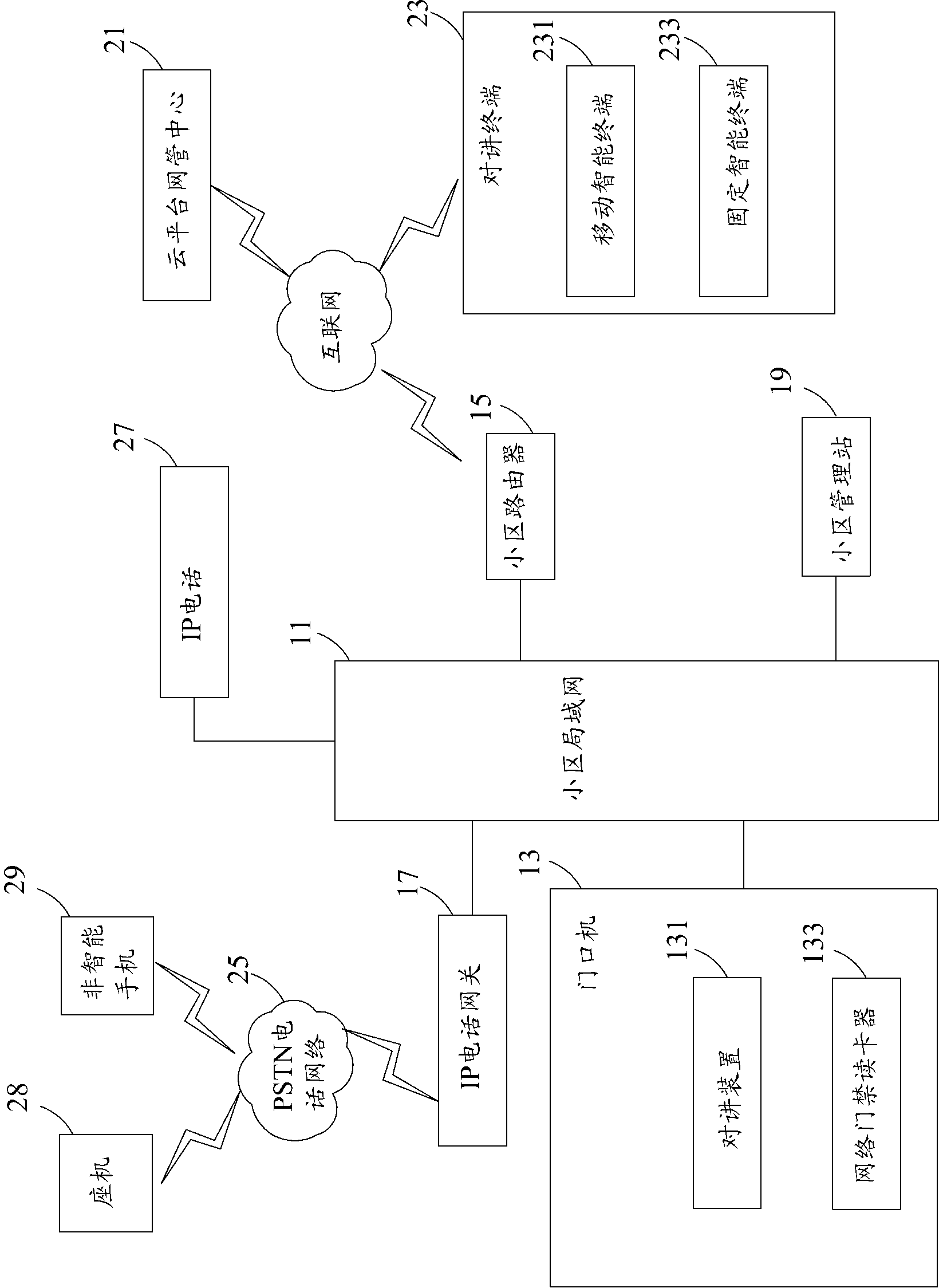
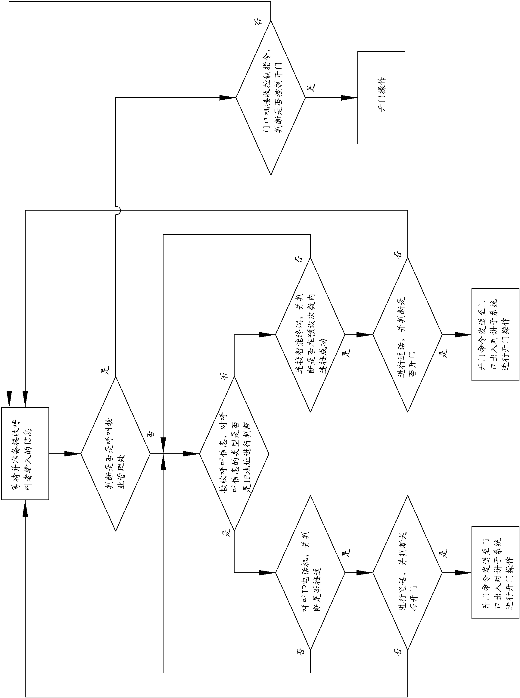
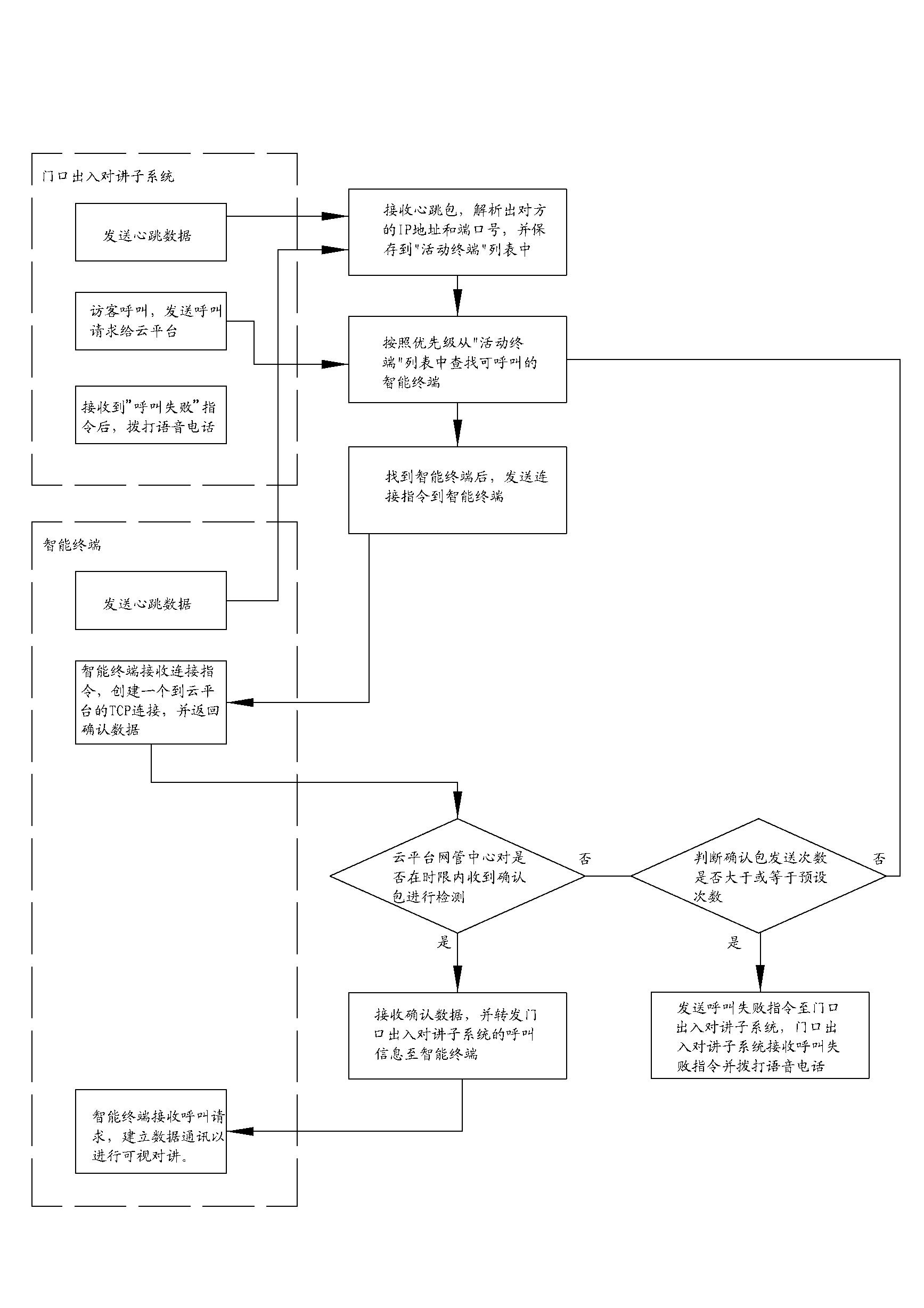
[0031] see Figure 1 to Figure 3 , The present invention provides a building video intercom system, including: a local area network 11, a door station 13, a router 15 in a residential area, an IP telephone gateway 17, and a management station 19 in a residential area. The outdoor station 13, the community router 15, the IP telephone gateway 17, and the community management station 19 are simultaneously connected to the community LAN 11 for communication. The building visual intercom system is also provided with a cloud platform network management center 21 and an intercom terminal 23 connected to the community router 15 through the Internet / mobile Internet and further connected to the community local area network 11. The intercom terminal 23 includes a mobile intelligent terminal 231 and an intercom terminal 23. Fix the smart terminal 233.

...


PUM


Abstract

The invention provides a visible intercom system for buildings. The visible intercom system comprises a community local area network, a doorphone, a community management station, an intercom terminal and a community router, wherein the doorphone and the community management station are connected to the community local area network for communication, the doorphone is used for performing the intercom operation and the door control starting operation, and the community router is connected to the internet through the community local area network. Components of the visible intercom system for buildings are connected to the internet through the community router, and a user is connected to the internet through the intercom terminal in any mode and perform data communication with other components, so that the user can achieve the intercom function conveniently through a universal smart phone/tablet personal computer which serves as the intercom terminal, and the defects of visible intercom system at present are overcome perfectly. The invention further discloses an intercom method for the buildings.

Description

technical field [0001] The invention relates to a building video intercom system and method. Background technique [0002] In the existing technology, the all-digital building video intercom system relies on the community LAN to realize functions such as management center, video intercom, access control, community information push, peripheral services, Internet access, communication in the community, smart home, security alarm, etc. However, the existing all-digital building video intercom system has the following defects: (1) The network operation cost is high, and the indoor unit realizes Internet services such as Internet access and peripheral services through the local area network of the community, and needs to pay an expensive Internet broadband interface rental fee. Compared with the Internet service that only provides indoor units, the cost is too high, and it is difficult for property management companies to accept it. (2) There are hidden dangers in network securi...

Claims


Application Information

Patent Timeline
Patent Type & Authority Applications(China)
IPC IPC(8): H04N7/14H04M11/02H04L29/08G07C9/00
Inventor 胡广江韦修毅李文辉符莎
Owner SHENZHEN HEGUANG MEASUREMENT CONTROL TECH
Why Eureka
Try Eureka