
Implant abutment

Inactive Publication Date: 2010-09-30
COCHLEAR LIMITED
View PDF31 Cites 14 Cited by
  • Summary
  • Abstract
  • Description
  • Claims
  • Application Information

AI Technical Summary

Problems solved by technology

A well known problem with percutaneous implants is the infections and inflammation at the skin-implant interface.
There is generally a lack of integration of the skin to the implant which results in a gap between the two.
This gap is unfortunately an ideal environment for the bacteria and if this zone is not properly managed, it is likely that an infection will occur.
It is also recognized that the effect that the shear forces has on the skin leads to tissue damage not only from a mechanical point of view but, more importantly, an indirect biological reaction which leads to foreign body reaction or dissociation from the material (encapsulation of the implant by fibrous tissue, etc).

Method used


Image

  • Implant abutment
  • Implant abutment
  • Implant abutment

Examples


Embodiment Construction

[0018]The present invention relates generally to bone anchored implant devices, and more particularly, to a percutaneous implant abutment for bone anchored implant devices adapted to be anchored in the craniofacial region of a person, such as bone anchored hearing aids. Implant devices of this type normally comprise a screw-shaped bone anchoring element (fixture) for permanent anchorage in the bone tissue and an abutment sleeve for skin penetration. The complete structure can either be in one piece or the skin penetrating abutment could be connected to the fixture prior, during or after the implantation procedure by means of a screw connection or the like.

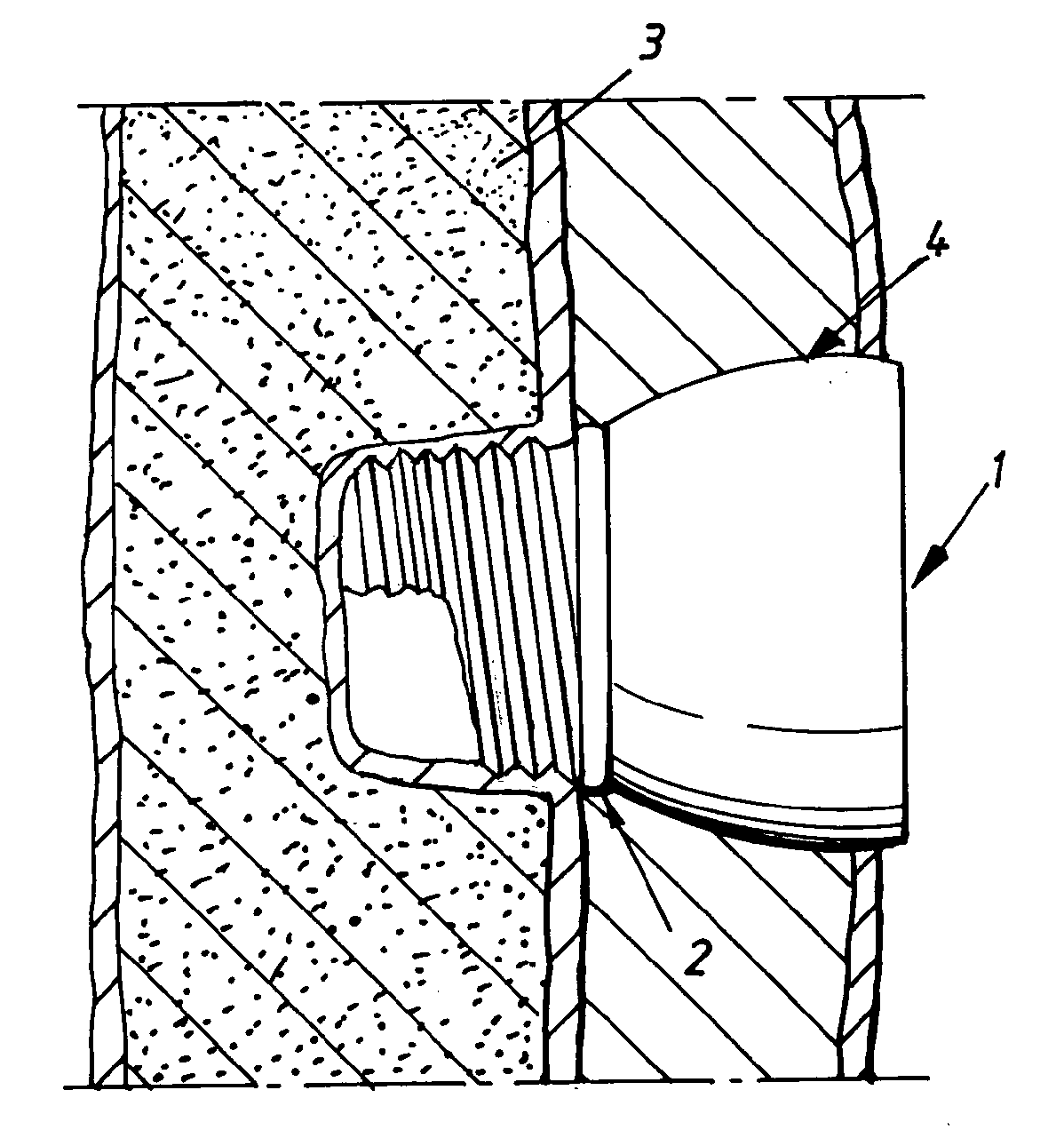
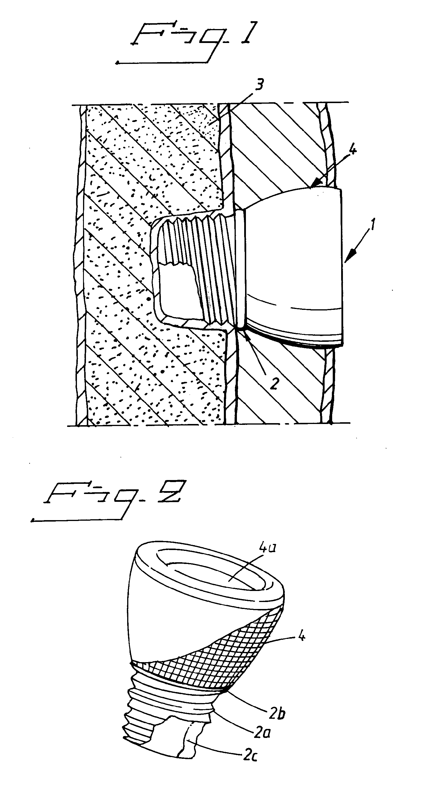
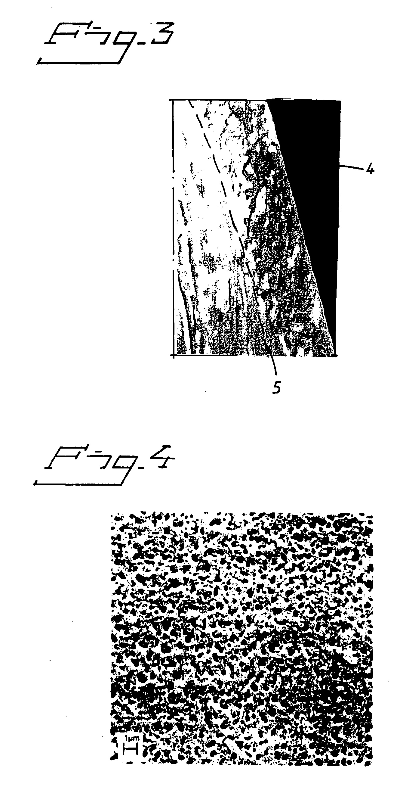
[0019]FIG. 1 illustrates a percutaneous implant 1 in accordance with embodiments of the present invention anchored in the bone in the cranio facial region of a person. The implant is may be used for a bone anchored hearing aid or the like. The implant comprises a screw-shaped bone anchoring element (fixture) 2 for permanent anchora...


PUM


Abstract

The present invention relates to a percutaneous implant abutment for bone anchored implant devices adapted to be anchored in the craniofacial region of a person, such as bone anchored hearing aids. The abutment comprises a skin penetration body having a skin contacting surface. The skin contacting surface has been modified.

Description

CROSS-REFERENCE TO RELATED APPLICATIONS[0001]This application is a national stage application under 35 USC §371(c) of PCT Application No. PCT / SE2008 / 000337, entitled “IMPLANT ABUTMENT,” filed on May 20, 2008, which claims priority from Swedish Patent Application No. 0701244-6, filed on May 24, 2007. This application is related to commonly owned and co-pending U.S. Utility Patent Application entitled “VIBRATOR FOR BONE CONDUCTING HEARING DEVICES,” filed Nov. 24, 2009, which is a national stage application of PCT Application No. PCT / SE2008 / 000336, filed May 21, 2008. This application is also related to commonly owned and co-pending U.S. Utility Patent Application entitled “ANCHORING ELEMENT” which is a national stage application under 35 USC §371 (c) of PCT Application No. PCT / SE2008 / 000338, filed on May 21, 2008. The entire disclosure and contents of the above applications are hereby incorporated by reference herein.BACKGROUND[0002]1. Field of the Invention[0003]The present invention...

Claims


Application Information

Patent Timeline
IPC IPC(8): A61B17/58
CPCA61F2/0077H04R2460/13H04R25/606A61F11/045A61L27/56H04R2225/67
Inventor ANDERSSON, MARCUS
Owner COCHLEAR LIMITED
Learn More