Air intake device for internal combustion engine
- Summary
- Abstract
- Description
- Claims
- Application Information
AI Technical Summary
Benefits of technology
Problems solved by technology
Method used
Image
Examples
first embodiment
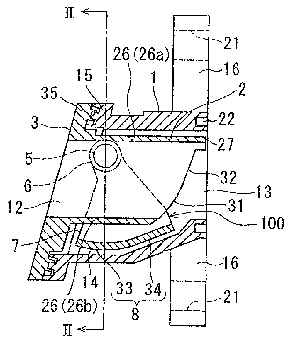
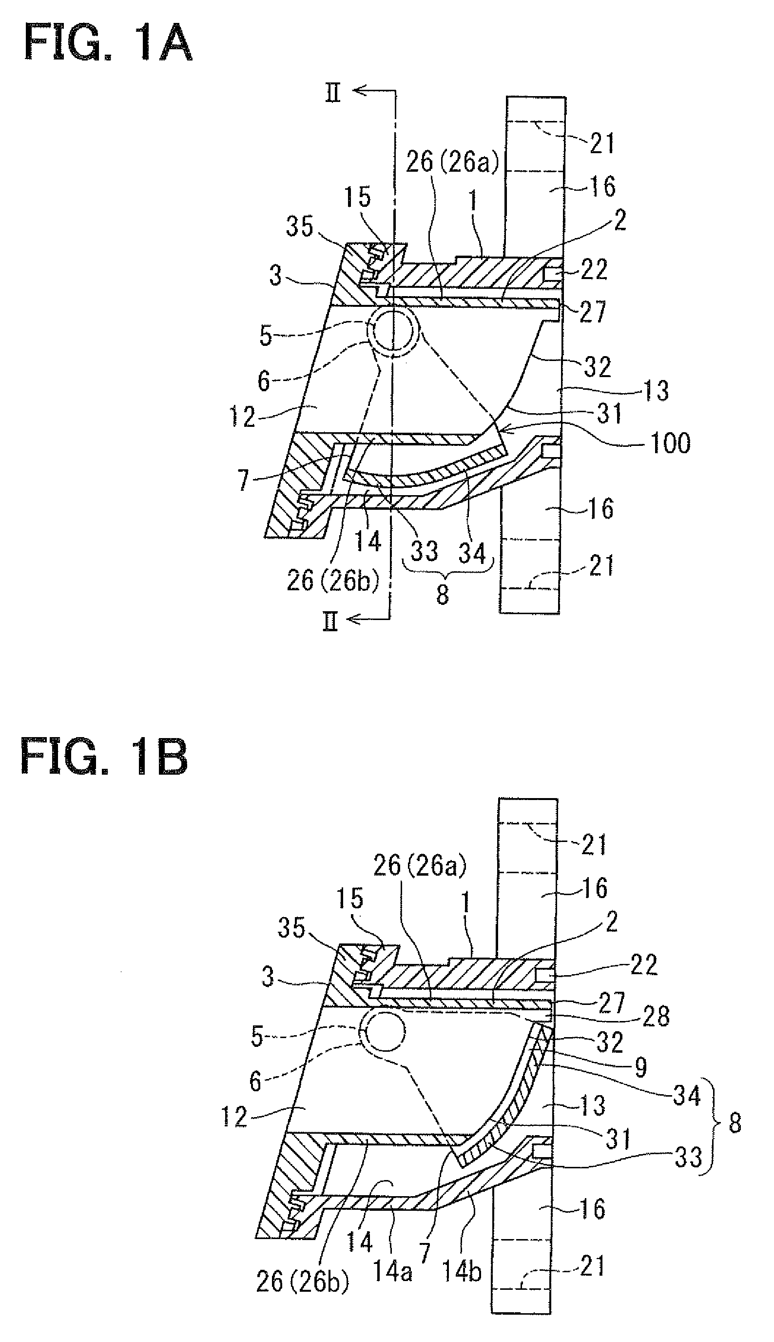
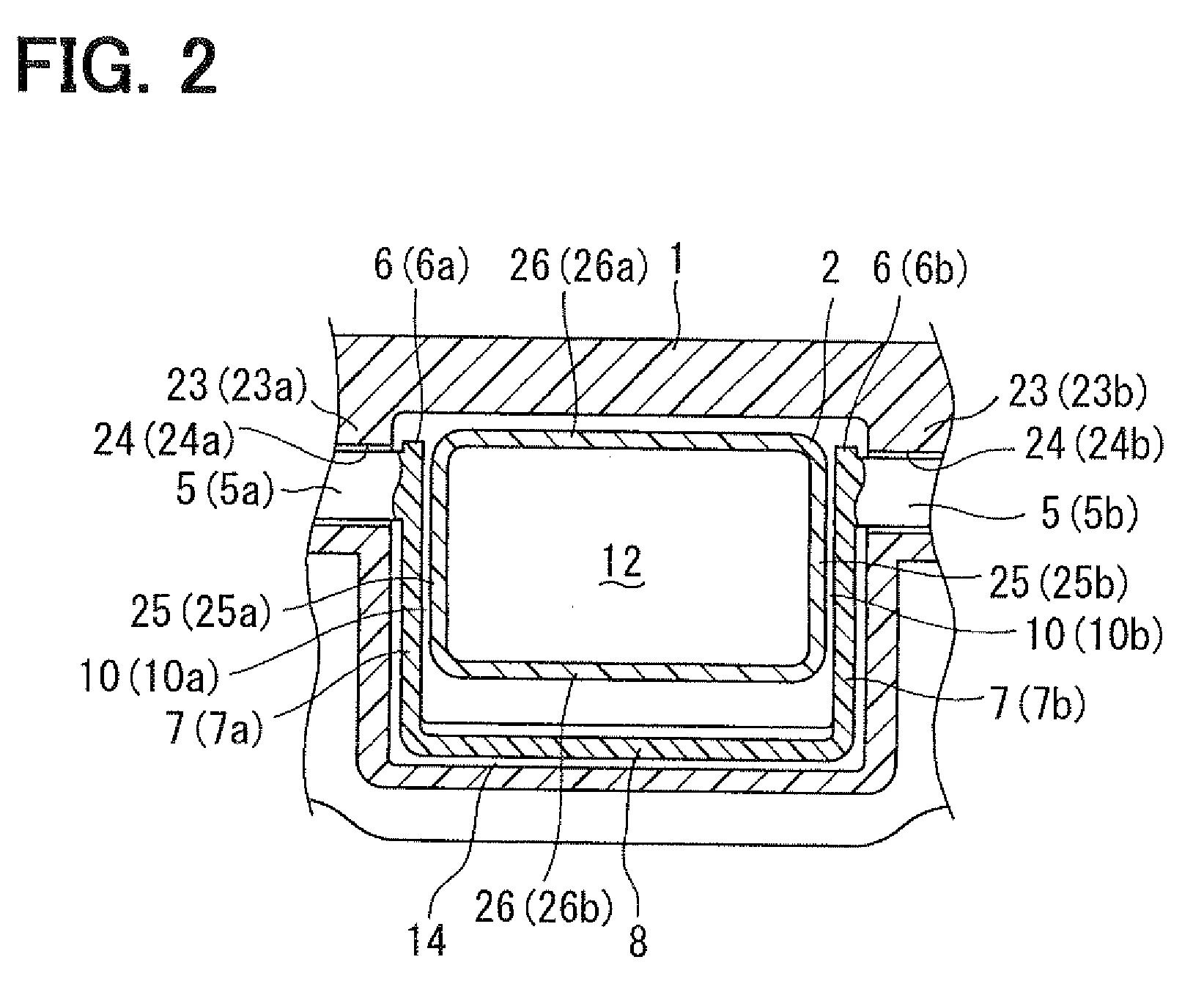
[0034]FIGS. 1A, 1B and 2 show a first embodiment of the present invention. FIG. 1A shows a valve condition of a rotary valve, which is accommodated in an accommodating space (that is, a valve opening condition). FIG. 1B shows a valve condition, according to which the rotary valve closes an air-intake passage (that is, a valve closing condition). FIG. 2 is a cross sectional view showing a valve unit, in which an air duct is provided inside of the rotary valve.
[0035]According to the present embodiment, an air intake device for an internal combustion engine having a plurality of cylinders has a plurality of valve units, each of which is accommodated within an air-intake pipe (air-intake duct) of the engine and used as an air-flow control valve (a tumble flow control valve). The valve unit is composed of a housing (having a valve block 1, multiple air ducts 2, and multiple valve covers 3) connected to a cylinder head (not shown) of the engine, a shaft 5 (for example, made of resin) rota...
second embodiment
[0100]FIGS. 3 to 5 show a second embodiment of the present invention. FIG. 3 is a front view showing a valve block 1 incorporating a rotary valve 100 according to the second embodiment. FIG. 4A shows the rotary valve 100 accommodated in the valve accommodating space 14. FIG. 4B shows the rotary valve 100 at its valve closed position. FIG. 5 shows the valve unit, in which the air ducts are assembled in the respective inside spaces of the valve block 1.
[0101]The valve unit of the present embodiment is composed of the housing (the valve block 1) connected to the cylinder head of the engine, the shaft 5 rotatably supported by the valve block 1, and the swing-type rotary valves (TCV) 100 attached to the shaft 5 at connecting portions 6. The shaft 5 has an outer cylindrical portion made of resin and a metal shaft portion 4 inside of the outer cylindrical portion. The shaft 5 having the metal shaft portion 4 is made by an insert-molding process.
[0102]The housing is composed of the valve bl...
third embodiment
[0121]FIGS. 6A and 6B show a third embodiment of the present invention. FIG. 6A shows the rotary valve 100 accommodated in the valve accommodating space 14 (the valve opened condition). FIG. 6B shows the rotary valve 100 in the valve closed condition.
[0122]Each of the side wall portions 25 (25a, 25b) of the air duct 2 has the downstream end, which is only formed with the curved portion 31 having the curvature radius at the shaft 5. The curved portion 31 extends from the duct extending portion 27 to the lower wall portion 26b.
[0123]Each of the rotary valves 100 has the pair of side plates 7 (made of the metal) outwardly extending from the shaft 5 to the free end in the radial direction. The valve plate 8 (made of the metal) is formed at the free ends for connecting the free ends of the side plates 7. As shown in FIGS. 6A and 6B, each of the side plates 7 has an L-shape.
[0124]The valve plate 8 of the rotary valve 100 has the curved surface portion 33, which faces to the downstream en...
PUM
 Abstract
Description
Claims
Application Information
 - R&D
- Intellectual Property
- Life Sciences
- Materials
- Tech Scout
- Unparalleled Data Quality
- Higher Quality Content
- 60% Fewer Hallucinations
Browse by: Latest US Patents, China's latest patents, Technical Efficacy Thesaurus, Application Domain, Technology Topic, Popular Technical Reports.
© 2025 PatSnap. All rights reserved.Legal|Privacy policy|Modern Slavery Act Transparency Statement|Sitemap|About US| Contact US: help@patsnap.com


